That's great new.
Also if I want to use diamond buffer configuration , but with 2x BUF634 parallel instead of discrete buffer for each channel to save space (for portable use like XEN ZGF portable) and use SSD heatsink for thermal control. Does it compatible? 2x BUF634 with 0.47 ohm at output will have about 4ohm Zout.
Another thing I want to try is whammy's output stage with opto and IRF610/9610 for desktop version.
I can do pcb design so no problem, but I'm not very good with the detail")
Also if I want to use diamond buffer configuration , but with 2x BUF634 parallel instead of discrete buffer for each channel to save space (for portable use like XEN ZGF portable) and use SSD heatsink for thermal control. Does it compatible? 2x BUF634 with 0.47 ohm at output will have about 4ohm Zout.
Another thing I want to try is whammy's output stage with opto and IRF610/9610 for desktop version.
I can do pcb design so no problem, but I'm not very good with the detail
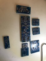
I finally started assembling SLHP amp!
I normally consider soldering as a therapeutic activity after a day in the office.
I have to admit that this time I got pretty stressed with those tiny little buggers!
Now the questions.
I see that for R21,22 which set the bias through the output stage Patrick suggests to use 10K trimmer and then replace it by smd resistors.
There seems to be not enough space for a 3296 series trimmer. Is the PCB made to fit any specific SMD trimmer package?
The other Q is about the output transformers. I have some D4H11/D45H11 probably enough for matching. Still they are listed as alternatives. Shall I go for the ones listed in the first place; 2SC4883/2SA1859?
I have found Patrick's explanation of trimming in posts #98 - #100 here (https://www.diyaudio.com/community/threads/the-pioneer-super-linear-circuit.313163/post-5290011)
I should have reread this thread before asking!
Matched and soldered jfets yesterday.
I should have reread this thread before asking!
Matched and soldered jfets yesterday.
I have some D4H11/D45H11 probably enough for matching. Still they are listed as alternatives.
Shall I go for the ones listed in the first place; 2SC4883/2SA1859?
You might find that the Sanken TO220's are next to impossible to get.
DK does not sell individual oney anymore. MoQ 1000 pcs.
They are better than the Onsemi's.
So if you have them / can find them, use the Sanken's.
Be aware there are after-market ones with the same number but not Sanken.
And of course plenty of fake ones around on ebay.
Patrick
I bought 50 2SA1312 and 100 2SC3324.Since we are on the topic, the very nice 2SC3324 / 2SA1312 are also obsolete.
I guess it was 2 yrs ago! So yes it took me a long time.
Solder one leg first.
Remelt if necessary for proper positioning.
Once you solder 2 or more legs, it becomes difficult.
Make sure you have fine solder wick to suck up excess solder.
I use 0.35mm solder with flux. And pointed tip.
Once you are used to it, it is easier than TH.
Patrick
Remelt if necessary for proper positioning.
Once you solder 2 or more legs, it becomes difficult.
Make sure you have fine solder wick to suck up excess solder.
I use 0.35mm solder with flux. And pointed tip.
Once you are used to it, it is easier than TH.
Patrick
Doing this alreadySolder one leg first.
That too. Filing the tips of my tweezers has helped a lot. Before that one one transistor has been soldered in it was almost impossible to position the one next to it.Remelt if necessary for proper positioning.
Totally agree.Once you solder 2 or more legs, it becomes difficult.
Haven't done it with this project. Will try.Make sure you have fine solder wick to suck up excess solder.
Yeah, I use 0.7mm solder. Too thick. Tried also solder paste but it does not easily stick to solder mask. I tend to apply too much. It turns out messier than with my solder wire.I use 0.35mm solder with flux. And pointed tip.
I use 0.5mm tip.
We shall see...;-)Once you are used to it, it is easier than TH.
I am trying to source the output transistors and some remaining parts.
Sanken 1859/4883 are indeed gone. As you said Patrick, DK sells one sex per pop, but the other one per 1000.
I sourced some known brands parts from LCSC from the big country in Asia before so I searched there as well. They seems to be able to back order 1859/4883 but from some unknown manufacturer so I better stay away from these...
Thanks. I have seen that there is still a chance to get them if you wait.
If I were to try to get them now from different sources there is always some mismatch ie npn is the A version and pnp non A.
I had a look at 2sc4381/2 and 2sa1667/8 too (are they good substitutes?) but again I can get one sort rated for higher voltage the other one not or I have to wait.
Well nothing wrong with waiting. I have waited a long time to start soldering.
Meanwhile UTHAIM is more than fine ;-) (though I underestimated the heat sink size - it runs at more like power amp temperatures)
The last point brings me to the question of heat sinking. I have the 2107 for this project with nice heat sinks on both sides. Still I see that everybody mounts power transistors to the bottom plate.
I understand that it allows better cable routing but it is a bit wasteful regarding the nice side heat sinks?
I understand that it allows better cable routing but it is a bit wasteful regarding the nice side heat sinks?
The bottom plate acts as a heat spreader and is thermally coupled to the heatsink with thermal conductive compound.
So it is not the bottom plate, but the heatsinks that are getting rid of the heat.
We are getting a batch of the Sankens, so you can get matched ones from us later.
But they will then not be 2.50€ a piece.
Patrick
So it is not the bottom plate, but the heatsinks that are getting rid of the heat.
We are getting a batch of the Sankens, so you can get matched ones from us later.
But they will then not be 2.50€ a piece.
Patrick
Hi
I finally managed to find some time to continue with the project.
I know it takes me a really loooong time.
Anyway I got CCS tested - works fine.
I got the main boards tested (but I have forgotten to check the current trough the output stage - D44H11 / D45H11).
I have checked the voltages around current sources all looked fine.
I have removed R9/10,R9a/10a , shorted R9a/10a, connected the CSS boards. Rechecked the voltages again around Q1-Q9 and their negative counterparts.
Looks good.
The only issue is it looks like I cannot turn on the output stage transistors. I get around 70-80mv at the base of Q11 and opposite at the base of Q12.
I have 10K trimmer for R21/22. Shall I replace it with a larger value to get higher voltage at the base of Q11?
I really wanted to run it by you as I do not want to mess up when the end is so near.
No, changing the 10k trimmer will do nothing.
As you adjust the trimmer, the voltage across the trimmer (or R21+R22) should change.
And you should be able to adjust it to at least 2.4V to turn on the output stage.
If turning the trimming does not do anything, then try 8.2k / 2k fixed resistors instead and see what voltage you get.
If you worry about burning your output transistors, remove R19,20 first during the test.
If all fails, then something else wrong with your build.
But if it works without the CCS before, then just use it without CCS.
As long as you have a good power supply, the difference is small.
Patrick
- Home
- Amplifiers
- Headphone Systems
- The Pioneer Super Linear Circuit