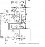
Figure 2.5 - A Typical Direct Coupled Transistor Amplifier
see this that i have copied
http://sound.westhost.com/amp-basics2.htm
and this about input
http://www.esafono.it/a700.pdf
see this that i have copied
http://sound.westhost.com/amp-basics2.htm
and this about input
http://www.esafono.it/a700.pdf
Attachments
Many thanks BV -->Very GOOD
you are a little genius
divide the functions is the best strategy
compensates for the differences effectively
in the current stage need just put other two LEDs on input
maybe need also two capacitors like A700 diy gene
your simulator can also put resistor's value?
")
you are a little genius
divide the functions is the best strategy
compensates for the differences effectively
in the current stage need just put other two LEDs on input
maybe need also two capacitors like A700 diy gene
your simulator can also put resistor's value?
Attachments
Stee, we are reinventing wheel or ligt bulb , it is nothing new on schematics.
Of course simulator can put values,
http://www.spectrum-soft.com/index.shtm
download, try it and learn to use.
, it is nothing new on schematics.Of course simulator can put values,
http://www.spectrum-soft.com/index.shtm
download, try it and learn to use.
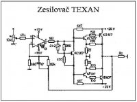
Amplifier called "Texan", about 1975. Date in picture is not "date of birth".
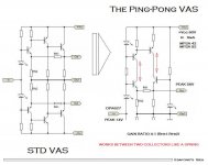
Maybe because it is not worth to use it...but i never seen that double local NFB in one commercial amplifier
Attachments
I don't think there is quite nothing new in these. You can look at the F5 from Pass which uses the exact same feedback scheme in his CFP output.
Actually, I am not sure it has any sort of advantage over the kind with only one feedback path in the middle. The simulation can tell if it's better or not, try it and let us know Stee. By the same way you can determine if putting emitter followers after the CFP is interesting distortion-wise, but I don't think it is since the gain is high enough in the usual CFP.
And after all, the best way to do a CFP could be with a total feedback (plain wire). Who really needs gain in the final stage? If you really want a gain of 4 after your opamp, you can also use a common base stage in between like in the musical fidelity amps.
http://www.diyaudio.com/forums/attachment.php?s=&postid=673432&stamp=1120201026
another OPA can solve this problem?
Hello to all
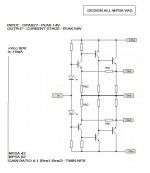
the purpose is not to set a gain (forcing a ratio on VAS)
the aim would be regular distinctly two branches (rails)
before they are added in the current stadium (stage)
to obtain two identical gains...
maybe use the primitive NFB is not a good idea
can solve this an operational from VAS
that can make difference and send result on input OPA?
Hello to all
the purpose is not to set a gain (forcing a ratio on VAS)
the aim would be regular distinctly two branches (rails)
before they are added in the current stadium (stage)
to obtain two identical gains...
maybe use the primitive NFB is not a good idea
can solve this an operational from VAS
that can make difference and send result on input OPA?
Attachments
- Status
- This old topic is closed. If you want to reopen this topic, contact a moderator using the "Report Post" button.
- Home
- Amplifiers
- Solid State
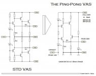
- The Ping-Pong VAS