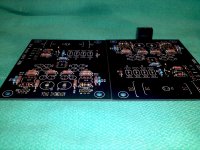
Soldered resistors in the VSPS last night. I used sockets at R2 and R3 so I can change resistors without desoldering and resoldering. Hope that works OK. Those boards from RJM took a little getting used to since they are thick and gold plated. They heated up a lot slower than the component legs so adjustments to my soldering style was in ordered. Finally got it sorted I think.
Attachments
I finished my phonoclone tonight.
It works but has major hum turned up.
It sounds pretty good.
With TT disconnected, can turn volume fully up and hear fairly faint white noise and hum, 50/50 (acceptable)
With inputs shorted, has major hum turned up. (same as w/24ohm cart across it)
Surprisingly, when I touch the input pin (no TT connected) it doesn't cause a scare you shitty hum.
The problem is equal for both boards/channels.
When the 2 boards were completed, I checked current draw for +/-, both boards; the positive side drew ~250mA/negative side ~50mA, (both boards).
All 4 power supply opamps get very hot-too hot to keep a finger on them very long. Q1 and Q2 are cool.
I'm using it w/.8mV/24ohm Benz cart and set the gain @~42db to tame it down a little and match my B&O MI levels on 2nd TT, so R1=24ohm/R2=100ohm.
What could I have overlooked/screwed up on both boards to cause this?
Last edited:
The power draw for the op amps is in the region of 5 mA each, circuit draw is about 20 mA per channel. 250 mA indicates a serious problem.
Disconnect the cart and move the phonoclone away from any audio equipment, to avoid damaging anything expensive.
Check you have right voltages at all the op amp pins. Should be about 9-12 V.
Both channels doing the same thing suggests a mistake in part placement. No smoke and a basically operating circuit suggests the error is a resistor with the wrong value rather than an improperly connected electrolytic capacitors or transistor. Not sure without more info, however.
Last edited:
Can you confirm that 5mA is the Power draw, or the quiescent draw when no output current is flowing?The power draw for the op amps is in the region of 5 mA each, circuit draw is about 20 mA per channel. 250 mA indicates a serious problem.
If a 5mA Iq opamp is outputting 10mAac to a load, then the supply rails will pass ~19mApk each, but alternately. Double that output loading to 20mAac (still within the limits of some opamps) then the supply rail current becomes ~32mApk.
That's typical DC current draw with the phonoclone circuit at zero output, but passing 2V rms to a 10k output load (typical operation) is not going to influence this estimate significantly. Anyway although 50 mA might be reasonable for the stereo pair, 250 mA is definitely not.
I tested them & all are OK.
Waiting to have some time to clean up the board and re-install them/see if all is OK. Will report then. Thanks.
PS-they weren't the least bit warm but the 2 opamps in the pwr supply were toasty.
Also-before prev post I checked all in & outputs for AC/DC: .000V
Waiting to have some time to clean up the board and re-install them/see if all is OK. Will report then. Thanks.
PS-they weren't the least bit warm but the 2 opamps in the pwr supply were toasty.
Also-before prev post I checked all in & outputs for AC/DC: .000V
Last edited:
The reason the op amps got toasty is that the emitter-base diodes were reversed, blocking any current flow in the pass transistors. The x-reg op amps were left to provide the circuit current, instead of just the control current. 24 V on the op amp, 20 mA current, that's half a watt and with no heatsink a DIP8 package is going to get too hot to touch... though not hot enough to be damaged, I don't think.
Wire Routing Suggestions
I've got almost everything in place but need some advice as to how to run the ground wires from the boards to the case/turntable ground. Should I twist up a pair and have them split into 2 separate wires at the center of the boards? Should I just run single wires around the case to the ground? Can I just run a jumper from 1 ground lug to the other and then run a single wire to the case? Are the grounding wires prone to pick up hum or am I worrying about nothing? I'm planning on grounding near the input jacks (bottom of the photo) so fewer cables have cross to opposite sides. Thanks in advance.
Dave
Attachments
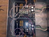
Ground wires are by definition low impedance and are therefore not sensitive to noise pickup.
I would run one wire from (R) GND to the case, another wire from (L) GND to the case, using spade lugs to connect the wires to the bolt at the case side so the boards can be disconnected easily later.
RJM Audio - Construction Guide
I would run one wire from (R) GND to the case, another wire from (L) GND to the case, using spade lugs to connect the wires to the bolt at the case side so the boards can be disconnected easily later.
RJM Audio - Construction Guide
Attachments
Last edited:
Q1 & Q2 were reversed and overheating pwr supply opamps/drawing high current..
Removed and properly installed Q1/Q2. Current & temp now OK.
Amp seems to work OK/clean except for hum level is quite high, but not audible except at very low/no music levels.
If inputs are open, hum is quite low-matched by white noise, and only audible at very high volume setting.
If inputs are bridged (shorted) hum is huge, at the level of what a music peak would be at the set volume level.
Since the opamps in the power supplies were overheated, I removed them from one channel and moved the gain opamps from the other channel over into their sockets in case they were damaged from overheating: no change.
I also checked AC V @inputs w/ my Fluke 88 lowest range, 400uV AC: it quickly settles at .1uV on both channels which I expect is close to true.
I have tried all the usual phono ground gambits learned in 40 years of trying to minimize it with little effect.
VSPS passed the smoke test today with flying colors. Perfectly silent, tight mid and bass. A little splasy top end my friends say but my high frequency hearing is poor so I didnt notice. This was in a friends system that I am unfamiliar with. I'll give it a listen in mine tomorrow! Thanks for all the help here.
Dave
Dave
If inputs are bridged (shorted) hum is huge, at the level of what a music peak would be at the set volume level.
Yes yes, the hum with the inputs shorted will be huge. That's how it will be with all phonoclones... how it should be. Remember the gain is R2/Zin. If Zin is zero ohms...
You may or may not hear a little hum with everything connected. It varies from user to user, as it depends on how well-shielded everything is all the way upstream to the cartridge, how tidy you are with the internal chassis wiring, etc.
Post some photos, and I can comment further...
Richard
Glider L2 or H2
Hi Richard,
I'm finshed almost my project I will show photo's later.
I have a question I can buy a second hand Benz Glider L2 or H2 what will be the best solution for the phonoclone?
I want to buy the H2 because for me cheaper.
But the gain will be then to high???
The L2 = 0.4mv en the H2 = 2.5mV
Hope you can help me out.
Thanks in advance
Ronald
By choosing the appropriate value for R2 you can get the circuit to work with either cartridge. The L2 is the "safer" choice, some high output carts have too high impedance to work with the phonoclone, but so far people have been having no problems.
Thanks Richard for your quick repliek I go for the L2.
I hardley can't wait to hear it.
Ronald.
Yes yes, the hum with the inputs shorted will be huge. That's how it will be with all phonoclones... how it should be. Remember the gain is R2/Zin. If Zin is zero ohms...
You may or may not hear a little hum with everything connected. It varies from user to user, as it depends on how well-shielded everything is all the way upstream to the cartridge, how tidy you are with the internal chassis wiring, etc.
Post some photos, and I can comment further...
Richard
OK, Richard. I'm leaving for a wedding and will be gone ~12 days. When I get back I'll post pics, but I'm a little confused. I think my lead dress and routing is good. Same cart/TT into Yamaha c2-x is quiet.
Thanks for your dedication to the underpriviledged of this community!
Phil
Hi Richard,
I'm finshed almost my project I will show photo's later.
I have a question I can buy a second hand Benz Glider L2 or H2 what will be the best solution for the phonoclone?
I want to buy the H2 because for me cheaper.
But the gain will be then to high???
The L2 = 0.4mv en the H2 = 2.5mV
Hope you can help me out.
Thanks in advance
Ronald
Here my Phonoclone with Saphire works perfect.
Use the cases from Hllyaudio.
4x Transformer 8x bridge and 2x Solid state relais to switch the transformers.
So the on/off switch from phonoclone/Saphire switch 5V to the solid states.
An externally hosted image should be here but it was not working when we last tested it.
An externally hosted image should be here but it was not working when we last tested it.
An externally hosted image should be here but it was not working when we last tested it.
- Home
- Source & Line
- Analogue Source
- The Phonoclone and VSPS PCB Help Desk