I prefer the Analog Devices version, which is actually a different circuit as far as I can tell from the datasheet. Not enough, however, to bother searching for it over the more widely available BB/TI version that, eg, Mouser stocks.
Thank you, but can you be more specific about the sound difference? I know DigiKey has the AD OP27GP in stock.
Ronald.
Richard,
I received the Phonoclone kit two days ago. Thanks for prompt shipment. I ordered the suggested components from Digi-Key for the power supply. A couple of questions raised by the instructions. 1) Should C18-21 be installed? 2) How does the statement "Z-Reg components should not ... when using an external supply" apply?
Warren
Was wondering the same thing for VSPS
The VSPS or the VSPS300? The former uses a dual op-amp chip, while the latter uses a single.
In my VSPS, I was running an FS NE5532 but then changed over to a BB OPA2134. After several days of listening I swapped back to the NE5532. I just found that it seemed to sound a little better to me. Maybe a little more detailed in the upper-mids, but I am not sure.
Of course YMMV, my old ears hear things differently than others.
-b
PS. I am not a universal believer in the "I can so hear differences in op-amps" school, but for low-level amplification circuits I would certainly expect small differences to be much more apparent.
@andrew
In terms of low noise, low distortion, manageable bandwidth, reasonably controlled input currents, good PSRR/CMRR figures, and, critically, availability in single, DIP8 packages, the OPA27 is still the best IC going for the Phonoclone input, and works fine in the remaining positions in that circuit and in the VSPS, where the noise figure is less critical.
Except for the Phonoclone IC1, for which I recommend the OP27, the other positions can be substituted with any "standard" spec audio op amp conforming to the NE5534, OPA134, etc.
People have tried various exotic op amps in the VSPS and Phonoclone, but without much success I have to say.
@bill
The op amp must be evaluated in the context of the circuit, the input impedances, gain, load capacitance, bypassing, etc. Between the NE5532 and OPA2134, the JFET input on the latter changes the electronic behavior considerably, and in my experience they sound quite different. I prefer the OPA134 over the NE5532 in the Sapphire headphone amp, but even in that same circuit, I could see other people preferring the more neutral, restrained sound of the the NE5532. For the VSPS, it's a completely different roll of the dice, so to speak.
Last edited:
1) Should C18-21 be installed? 2) How does the statement "Z-Reg components should not ... when using an external supply" apply?
1) No. Only needed when trying to stabilize high bandwidth op amps.
2) Sorry, typo. Should read "X-Reg components should not ... when using an external regulated power supply" By which I mean, if you want to use batteries or your own voltage regulator design, what you do is leave all the X-reg parts off the Phonoclone board and feed the board from the V+ V- pads rather than the V++ and V-- pads. For the standard build, the V+ and V- pads have the X-reg output voltage on them, and can be just used as test points.

I was browsing the VSPS project page trying to decide if I need more gain, and I noticed something weird.
Couldn' t we feed the negative phase of the cartridge into the Inverting input of the op amp?
That would give us the benefit of using the op amp in its native inverting state. Kind of like a one stage phonoclone.
I hope I m not missing something really noobishly...
Couldn' t we feed the negative phase of the cartridge into the Inverting input of the op amp?
That would give us the benefit of using the op amp in its native inverting state. Kind of like a one stage phonoclone.
I hope I m not missing something really noobishly...
In an inverting configuration, the input resistance is in series with the source, since the op amp's inverting input is a virtual ground.
This is great for the phonoclone stage, but lousy for the VSPS because moving magnet cartridges require about a 47k input load. If you put 47k on the inverting terminal, that's the input impedance seen by the op amp. The op amp gets really noisy. Might be doable with a JFET input op amp, but really I don't think it is ideal.
This is great for the phonoclone stage, but lousy for the VSPS because moving magnet cartridges require about a 47k input load. If you put 47k on the inverting terminal, that's the input impedance seen by the op amp. The op amp gets really noisy. Might be doable with a JFET input op amp, but really I don't think it is ideal.
Richard,
I've been told that the power supply and phono stage can share a common enclosure, but the power supply must be away from the cartridge. If, how much separation is sufficient?
Can the power supply be left "on" when the phono stage is not in use (heat, etc.)?
This information will help me decide how to box the components.
Thanks
The power supply can be left on, there is minimal power draw. <1W.
Some cartridges are particularly sensitive to magnetic interference. Grados for instance. The amount of interference also depends on the transformer size, type, orientation, and whether magnetic shielding is used.
Transformer and power supply components can also induce noise by capacitive coupling if the phono boards input wires are close by and unshielded.
If you are using a common enclosure, I suggest full width 1U chassis with the power supply one side and the boards the other, and a metal internal divider.
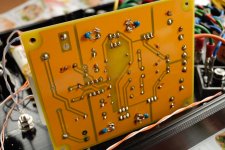
Important update to the B-board saga.
Round 2: I switched out the B-Board for a second set I made with some changes to the BOM. I also modded my Sapphire headphone amp with ceramic bypass caps. Short story: they both sound much better now, less brittle, more relaxed and musical.
Test A: as before, headphones, straight from phonoclone3 or routed through B-board based preamp. Tried both setting the B-board attenuator at 100% and using the Sapphire volume control, and setting the Sapphire at 100% and using the B-board attenuator.
Result: Must less difference than before. Through B-board, sound is richer, fuller, with more weight and width. Straight through, it's nice, but just a little less full, with more accent on the treble. Finally, I preferred the sound with the B-board, operating as a premp (i.e. using the B-board rather than the Sapphire to control the volume.) Using the Sapphire attenuator the sound was just ever so slightly more indistinct.
Test B: I modified my 47 Labs 0247 headphone amp such that the line out is taken from the output of the 50k Alps pot. It becomes a passive pre, in other words. So I could compare my 47 Labs 0347 amplifier driven by the B-board pre vs. a 50k potentiometer.
Result: B-board is just far and away better. Switching in the 0247 (passive) it's like the bottom end just deflates. Sound is weak, drained of color and vitality.
Ceramic capacitors. A small change that turns my previous judgments on their head.
Anyway I'm completely sold now both on active preamps and the B-board.
However, I could make out a difference. No B-board, the sound was slightly weaker and more distant, but at the same time more accurate in the delineation of the stereo image.
Round 2: I switched out the B-Board for a second set I made with some changes to the BOM. I also modded my Sapphire headphone amp with ceramic bypass caps. Short story: they both sound much better now, less brittle, more relaxed and musical.
Test A: as before, headphones, straight from phonoclone3 or routed through B-board based preamp. Tried both setting the B-board attenuator at 100% and using the Sapphire volume control, and setting the Sapphire at 100% and using the B-board attenuator.
Result: Must less difference than before. Through B-board, sound is richer, fuller, with more weight and width. Straight through, it's nice, but just a little less full, with more accent on the treble. Finally, I preferred the sound with the B-board, operating as a premp (i.e. using the B-board rather than the Sapphire to control the volume.) Using the Sapphire attenuator the sound was just ever so slightly more indistinct.
Test B: I modified my 47 Labs 0247 headphone amp such that the line out is taken from the output of the 50k Alps pot. It becomes a passive pre, in other words. So I could compare my 47 Labs 0347 amplifier driven by the B-board pre vs. a 50k potentiometer.
Result: B-board is just far and away better. Switching in the 0247 (passive) it's like the bottom end just deflates. Sound is weak, drained of color and vitality.
Ceramic capacitors. A small change that turns my previous judgments on their head.
Anyway I'm completely sold now both on active preamps and the B-board.
Attachments
No I haven't. I'm kinda hoping that other are prompted to experiment a little. Basically, except for the diamond buffer in the B-board/Sapphire every other circuit I've made is low bandwidth and should therefore not need to be bypassed in this way.
However, I was fairly certain - before I tried it - that bypassing wouldn't have much effect on the diamond buffer either, so all bets are off....
However, I was fairly certain - before I tried it - that bypassing wouldn't have much effect on the diamond buffer either, so all bets are off....
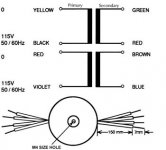
Richard, blowing fuses in my power supply. Using the suggested Amveco transformer. Saw your advice to connect connected outputs to either ~ side of the same rectifier, found green & red had continuity as did brown & blue. Data sheet instructs "for 115v operations, connect primaries in parallel by connecting yellow and red lead wires together and black and violet leads wires." so connected y/r pair to L and b/v to N. Suspect I made a mistake with primaries. Appreciate assistance.
Thanks,
Warren
Thanks,
Warren
link
Technically black/violet goes to L rather than N, but this isn't a catastrophic mistake and your description of the transformer connection is otherwise correct.
I would suspect, therefore, that you are using a quick-blowing fuse, which will trip on the inrush currents.
Technically black/violet goes to L rather than N, but this isn't a catastrophic mistake and your description of the transformer connection is otherwise correct.
I would suspect, therefore, that you are using a quick-blowing fuse, which will trip on the inrush currents.
Attachments
- Home
- Source & Line
- Analogue Source
- The Phonoclone and VSPS PCB Help Desk