Hi,
Since I can't know what you do and dont understand about it, its hard for me to answer...
On one level, there is no reason you need to understand it! Just use Rf=1k first and afterwards adjust to match your system. If you prefer to set the gain specifically, the formula is given, and accurate enough to be useful. If you have a 5 ohm cart, and want only 40dB (100x) gain, then Rf=5x100=~470ohms. (1k would give 46 dB in the first stage.)
Increasing the complexity of the explanation just treat the system as a voltage source (approximately the list cartridge output voltage) feeding a classic inverting stage with an input impedance of Rs.
The reason you can do this is that Rs and Rin are in series and thus equivalent and interchangeable. (10 ohms + 100ohms = 100 ohms + 10 ohms).
One can of course look at the system as a current source feeding a zero impedance I/V converter, but as I wrote on the homepage, cartridges are usually treated as voltage, not current sources and I find is simpler to keep to that convention.
/R
rjm said:Since the output is AC coupled through C3, the DC offset is zero by definition. If you are measuring the DC offset at the output of the second op-amp, before the cap, it will depend on the op-amp and gain, and will likely be in the order of 100s of mV.
/R
Dear Richard
Sorry! my mean was measuring line output(after C3 ),
I measuring second Op output after C3 have DC offset over 2mV~250mV
One of three things:
1. C3 is defective, or you used a polar electrolytic by accident, etc...
2. R7 is much larger than 33k, or not properly connected.
3. (most likely) you wrote "under play", ie. with music playing. In that case the meter will likely pick up the low frequency music signal in the readout, even in "DC Volts" mode. Try measuring without an LP spinning.
..sigh
/R
When Lp spinning was 0.0mV
I dont see the problem then. It doesnt make any sense to measure the offset with music playing.
Update Bulletin no 1. Power Supply Capacitance
I am changing the recommended capacitance on the input to the voltage regulators from the 100uF-220uF originally stated to 330uF-470uF per regulator. This applies to both the Phonoclone and the VSPS, but only when unregulated supplies without additional capacitance are used.*
I increased C8-11 on the phonoclone PCB from 100uF to 470uF and noted an improvement in control, power, and drive, with no loss in speed, clarity or timing. On the measurement side, this is just sufficient to hide the power line noise below the broadband op-amp noise, though I admit that the noise, with the volume all the way up, didn't sound any different than before.
Remember that adding about the same amount of capacitance further away from the PCB completely destroyed the sound in the speed/timing department. I conclude, like many before me, that the capacitance has to be as close as possible to the op-amp.
I'll update the web pages shortly.
Richard
*Obviously if the supply is regulated, and/or has additional filter capacitance, then the power supply noise going into the PCB is much less and there is no need to increase the capacitance on the PCB. Increasing capacitance increases the stress on the diodes and transformer, increases the charging current, and increases the high frequency components of the ripple. With the Phonoclone PCB (current revision), you must re-route the ground of C8-11 as discussed earlier if you increase the capacitance, as the shared ground problem when using the filter capacitor in the normal position will get worse as the charging current increases, and noise performance will actually get worse not better!
**I will make a new PCB revision of the Phonoclone before the next batch order to fix the grounding issue. Most likely it will be double sided, with one side for the power supply ground plane and the other for the signal.
The higher caps for bypassing are fitting with my findings:
Operating the VSPS with batteries resulted in a lack of bass, compared to my regulated psu. After adding 2 x 1000uF low ESR bypass caps nearby the battery the problem was solved.
BTW: I just received some mica caps and immediately replaced the polyprop caps in my phonoclone with the micas: the result is great! Much clearer highs, more details.
Franz
A small update:
I replaced the 12V regulators with 9V types (7x09's) on the input stages of the phonoclone. Earlier, some people had reported that the lower voltage was less noisy.
I haven't measured it yet, but to my ears there isnt any significant difference to the (already low) noise level. There is a subjective sense of increased midrange clarity, but its subtle to the point where I start to have doubts there was any difference at all.
Since my findings were neutral//slightly positive, I will replace the output regulators as well at some point.
Until then I'll put a YMMV stamp on it.
/R
The VSPS at the ETF05
This weekend, I compared a VSPS at the European Triode Festival with 23 other RIAA preamps.
It was a shooutout, just for fun and not delivering "absolute" results.
In the first round, the amps got paired by random. So, we compared two amps at time. Every amp was playing randomized music for 2 times 45 seconds.
The second round followed the same rules, but the votes where counted and the winners reduced to just four amps, for a semi final and a final round.
In the first round, you could have good luck and let your amp play against a "bad" amp (some amps hummed for example).
So, in the first round, my VSPS played "against" a tube amp from John Atwood, a very good amp. I did not have many votes less than John.
Gerald Gessner, a very well known man in the scene (CD tweaking for example), took part at the shooutout with a concept nearby a phonclone: inverting input (AD797) with little gain and correction of the first time constant in the feedback, then passive eq of the second time constant and a OPA134 with gain in the output. He got it in the second round, but then a technical problem shoot it out.
BTW: technical problems...
Allen Wright measured every amp the night before for gain and RIAA equalisation. They wanted to use the gain measurement to adjust the volume to compare all amps at the same level. But this did not work, as the amps should have been measured and leveled by microfone direct before the test track.
The shooutout asked for an amp with a gain from 40dB, 47k input (Benz Ebony HO) and 100k output. The samples varied between 27dB and about 60dB!!
My amp worked exactly with 40dB. It is based on an own pcb, OPA134, mica caps and battery powered. But with LM317/337 regulator, at about +/- 12VDC.
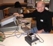
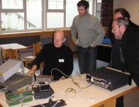
The picture is showing Allen Wright measuring my amp. He was impressed about the accuracy of the RIAA curve, not knowing the concept or beeing aware of his own "modification" inside.
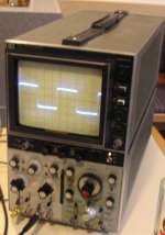
You see a exactly square wave on the scope. The signal is fed through a "anti RIAA" equalizer and then through the VSPS.
The competition was won by the end from a tube amp from Peter van Willenswaard, as the "Little Sis" from Steve Bench stopped working with a loud plop. In the last two rounds, it got very difficult, to vote for one amp or the another.
It showed me, that the VSPS is playing at a very high quality level, comparable to every top RIAA pre!
All in all: it was big fun! Many thanks, Richard, for your nice reverse engeneering and simulations and your advices per mail to prepare my "competition amp".
Franz
This weekend, I compared a VSPS at the European Triode Festival with 23 other RIAA preamps.
It was a shooutout, just for fun and not delivering "absolute" results.
In the first round, the amps got paired by random. So, we compared two amps at time. Every amp was playing randomized music for 2 times 45 seconds.
The second round followed the same rules, but the votes where counted and the winners reduced to just four amps, for a semi final and a final round.
In the first round, you could have good luck and let your amp play against a "bad" amp (some amps hummed for example).
So, in the first round, my VSPS played "against" a tube amp from John Atwood, a very good amp. I did not have many votes less than John.
Gerald Gessner, a very well known man in the scene (CD tweaking for example), took part at the shooutout with a concept nearby a phonclone: inverting input (AD797) with little gain and correction of the first time constant in the feedback, then passive eq of the second time constant and a OPA134 with gain in the output. He got it in the second round, but then a technical problem shoot it out.
BTW: technical problems...
Allen Wright measured every amp the night before for gain and RIAA equalisation. They wanted to use the gain measurement to adjust the volume to compare all amps at the same level. But this did not work, as the amps should have been measured and leveled by microfone direct before the test track.
The shooutout asked for an amp with a gain from 40dB, 47k input (Benz Ebony HO) and 100k output. The samples varied between 27dB and about 60dB!!
My amp worked exactly with 40dB. It is based on an own pcb, OPA134, mica caps and battery powered. But with LM317/337 regulator, at about +/- 12VDC.
The picture is showing Allen Wright measuring my amp. He was impressed about the accuracy of the RIAA curve, not knowing the concept or beeing aware of his own "modification" inside.
You see a exactly square wave on the scope. The signal is fed through a "anti RIAA" equalizer and then through the VSPS.
The competition was won by the end from a tube amp from Peter van Willenswaard, as the "Little Sis" from Steve Bench stopped working with a loud plop. In the last two rounds, it got very difficult, to vote for one amp or the another.
It showed me, that the VSPS is playing at a very high quality level, comparable to every top RIAA pre!
All in all: it was big fun! Many thanks, Richard, for your nice reverse engeneering and simulations and your advices per mail to prepare my "competition amp".
Franz
Attachments
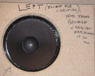
And a funny thing: the shootout asked for a DIN input. The amp could have RCA input, an adapter made by Allen was available.
The organisator, Christian, was misunderstood by most people with his description about the pin wiring.
I realized the confusion before the festival and asked Christian per mail.
The result: my amp and the amp from Christian where the only ones with correct left/right wiring.
Of course, the marked the other amps for competition and reversed the outputs of this amp.
But you may have a look at the left baffle...
Attachments
- Home
- Source & Line
- Analogue Source
- The Phonoclone and VSPS PCB Help Desk