The VSPS Kit Thread though the main info is still on the pcb page.
An externally hosted image should be here but it was not working when we last tested it.
Richard,
I have ordered the VSPS300 boards and I have a query about the gain setting and load resistors. My cartridge is a Denon DL103 running into either a CineMag SUT (BobsDevices) or a Denon HA-500 Headamp; so the question is how do I work out what the load / gain should be?
Thanks
Alan
I have ordered the VSPS300 boards and I have a query about the gain setting and load resistors. My cartridge is a Denon DL103 running into either a CineMag SUT (BobsDevices) or a Denon HA-500 Headamp; so the question is how do I work out what the load / gain should be?
Thanks
Alan
Hi Alan,
The logical thing to do is retire the headamp and build a phonoclone instead, which directly connects to the DL-103.
If you really want to use a VSPS for some reason (more flexibility to use with MM carts in future for instance), build it with the standard gain and load given in the BOM / project page: 40dB and 47k.
Richard
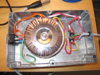
I was doing up a couple of new diagrams for the VSPS Kit. The basic drawing of the power supply (below) showed me something about using two bridge rectifiers that I hadn't thought about before:
Its idiot proof.
If the transformer has two separate windings, all you need it identify each one (continuity check) and each secondary connects to the ~ markings of a rectifier. There is no worrying about the phase of the output wires.
The rectified + and - connections are also pretty straightforward, as it stacks head to tail in a logical way.
For your reference the transformer of choice is Talema 62072 or Talema 62082 and the rectifiers of choice Vishay Glass Passivated GBPC 602-E4/51GI, though anything from that series will be fine.
I like those square donut rectifers as the mounting hole is convenient for attaching them to the case.
Built in external chassis, these things are really great little modules as they can power just about op amp audio circuit you care to build, and can be conveniently stacked for dual mono as required.
/R
Attachments
Output cap ?
Hi,
I wonder, why in almost all opamp based phonostages output caps are used?
I now, for DC blocking.
I haven't build opamp phono yet (only FET based Phono), however I have large experience with CMoy type headphones amps. With FET input opamps, like OPA2132 DC offset usually is 0.5-3 mV, 7mV max.
I believe source (MM cartridge) can't produce any DC on phonostage input too.
So, my question is - do I really need output cap, if I use FET input opamp?
Thanks,
Zigis.
Sennheiser specify music signal at 1Vac for max 115dB SPL for my new headphones.
2V takes the output to an equivalent of 121dB if we could hear DC, but the headphones can and will.
0.02V (=20mV) would be equivalent to 81dB. I don't think I would like to mix that in with my music signal.
2V takes the output to an equivalent of 121dB if we could hear DC, but the headphones can and will.
0.02V (=20mV) would be equivalent to 81dB. I don't think I would like to mix that in with my music signal.
Ground loop breaker circuits on power supplies
RJM/MJL21193, here is a nice article on earthing audio equipment (http://sound.westhost.com/earthing.htm) including a bulletproof diode-bridge ground loop breaker circuit (I have used this a number of times, it works). On the same site is another salutory artcle on electrocution by the same author (http://sound.westhost.com/articles/electrocution.htm) that I re-read from time to time, just to remind me how much I like listening to music, tinkering with circuits, being alive and enjoying my family.
RJM/MJL21193, here is a nice article on earthing audio equipment (http://sound.westhost.com/earthing.htm) including a bulletproof diode-bridge ground loop breaker circuit (I have used this a number of times, it works). On the same site is another salutory artcle on electrocution by the same author (http://sound.westhost.com/articles/electrocution.htm) that I re-read from time to time, just to remind me how much I like listening to music, tinkering with circuits, being alive and enjoying my family.
Hello to all,
first.. thank you very much RJM, for the excellent work on the site! The tutorial is great, and everything explained in great detail
I was thinking building the VSPS, but since I don't know much about electronics, I wanted to ask if it is possible to put a volume potentiometer on it? if it is, I could I connect it?
Thank you in advance!
athanor
I wanted to ask if it is possible to put a volume potentiometer on it?
In essence this amounts to putting a passive preamplifier into the VSPS chassis, the volume pot goes between the VSPS board and the RCA output jacks.
It has all the disadvantages of a regular passive preamp, but it will let you hook the VSPS to an amp directly.
Thank you, rjm, for the quick replay. I was just wandering, is there any calculation necessary for me to find the correct value of the potentiometer? I mean, I guess it must be based on the out impedance of the VSPS, and the input impedance of the equipment I want it to be connected. I this correct?
Thank you again,
athanor
Thank you again,
athanor
phonoclone
Hi guys, question re PSU for phonoclone-
i 've built one using 100VA 2+12VAC toroid-
the measured Voltage after rectifier is 11.5. Is there a problem? I thought it is a bit low.-was kind of expecting 18 or so.
recheck again-fuse blown-must be short somewhere.
Hi guys, question re PSU for phonoclone-
i 've built one using 100VA 2+12VAC toroid-
the measured Voltage after rectifier is 11.5. Is there a problem? I thought it is a bit low.-was kind of expecting 18 or so.
recheck again-fuse blown-must be short somewhere.
Last edited:
here is a picture.
hi,quan
where to buy the toroid in aus.
Specialist in machinery technology
www.greatinfo.com.au
Last edited:

- Home
- Source & Line
- Analogue Source
- The Phonoclone and VSPS PCB Help Desk