Back again,
There she plays! I was slightly worried at first when i hooked this to the small Audio Pro Addons i have for the missus laptop. Something in the active side of those spekaers made a ever so small hiss of sort.
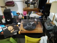
Currently playing from HIFIMEDIY T1-M TK2050 stereo amp i have cued for a portable boombox. Power from mascot 12vdc 1.3a general transformer. I changed to my amphion argon 1s with this. TT is a Project Audio made with blue point n. 2, FYI for those interested.
And as you can see from the picture nothings is nice and tidy on the test setup, wires crisscrossing around, ac there dc here, rca between etc xD but i'm happy to report no hiss nor buzz neither no hums nor anything off what so ever. Only the happy clips you get from old LPs.
I'll update again when i get this fixed to my main system. And have the box finalized.
There she plays! I was slightly worried at first when i hooked this to the small Audio Pro Addons i have for the missus laptop. Something in the active side of those spekaers made a ever so small hiss of sort.
Currently playing from HIFIMEDIY T1-M TK2050 stereo amp i have cued for a portable boombox. Power from mascot 12vdc 1.3a general transformer. I changed to my amphion argon 1s with this. TT is a Project Audio made with blue point n. 2, FYI for those interested.
And as you can see from the picture nothings is nice and tidy on the test setup, wires crisscrossing around, ac there dc here, rca between etc xD but i'm happy to report no hiss nor buzz neither no hums nor anything off what so ever. Only the happy clips you get from old LPs.
I'll update again when i get this fixed to my main system. And have the box finalized.
Attachments
Hi Richard, I've just known this information.
So do you have suggestion for optimum value of R1, R2 for the Denon 103, and 302 to replace current value that I am using R1=47.5ohm; R2=1Kohm (Rev 35h kit).
Denon 103 (0.3mV) and 302 (0.18mV) both have catridge output impedance = 40ohm.
Thank you.
So do you have suggestion for optimum value of R1, R2 for the Denon 103, and 302 to replace current value that I am using R1=47.5ohm; R2=1Kohm (Rev 35h kit).
Denon 103 (0.3mV) and 302 (0.18mV) both have catridge output impedance = 40ohm.
Thank you.
I grabbed all the available cartridge data on the vinylengine database and had a look in excel to see what the statistics looked like.
The answer I got surprised me: the Denon DL-103 is NOT a typical MC cartridge. If you rank them by current output, the DL103 and many other Denon models are outliers, with about 4x less current than is typical.
The median voltage sensitivity is 0.4 V, with the median DC resistance of 11 ohms. The median current output is 33 microamps, compared with just 7 microamps for the DL103. Current output directly determines the size of the phonoclone R2 value.
In terms of the optimal value of R2 then, as the histogram shows most cartridges fall between 100 and 300 ohms, with about an equal number above and below that range. The most typical value of R2 would therefore be about 221 ohms.
You would typically want to operate the phonoclone with a value of R2 less than a factor of two from the ideal value for the cartridge used.
So do you have suggestion for optimum value of R1, R2 for the Denon 103, and 302 to replace current value that I am using R1=47.5ohm; R2=1Kohm.
Most likely both carts will work fine with the 47.5/1k. There's no need to change anything unless the gain is too high or too low.
Important notice.
The post office told me today that that a fair chunk of countries around the world are not accepting packages from Japan. Meaning I won't be able to ship your orders.
Fortunately I have none outstanding, and of this writing the US and Canada are still accepting mail. Most European countries are not, however.
I light of this RJM Audio will not be taking new orders until further notice.
Hi Richard
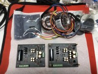
I just came into a partially finished VSPS 300m with what looks like almost everything I need to finish it. I attached a pic of the boards, transformers and extra op amps. I also got some other items to help finish it like IEC inlets and some nice Rane RCA sockets.
It looks like I basically need to come up with two cases and make all the connections assuming there’s no issues with the boards as they are populated.
I bought this with the intention of trying to substitute it where I am using one of the Boozehound Labs jfet phono amps.
I have the Boozehound running off of a rechargeable NiMH power supply and wired so I can switch a ZYX head amp in and out in front of it so that I can use MC cartridges with the head amp and just the jfet phono amp with my MM carts.
I’d like to know if there would be any issues trying to do the same with this VSPS albeit with the transformer based supplies. I would build it with two supplies, one for each channel.
I’ve used the search on this thread and Googled RJM Audio 300m and got very few hits and none of which that could give me specifics about this particular version of the VSPS.
I did read the various assembly guide info on your website, but it seems focused on building the dual board Emerald. The VSPS supported is the single board version.
Can you provide me any specific information regarding how this version should be assembled with its supply and any specifics about implementation regarding compatible or incompatible carts.
Also information about gain structure and what the result of implementing the extra op amp at C1 results in would be great.
I suppose the easiest thing might be a pdf if there was one archived That you could send me.
Any help you could provide would be great.
Attachments
@chromenuts
That's a kit that someone has put together but, I suppose, never built.
The main thing you are missing, besides the case and connectors, is the bridge rectifier.
Everything about hooking up Emerald or Phonoclone applied to this version of the VSPS also. The VSPS300 is a carbon copy of the Phonoclone 3, but with the VSPS circuit substituted for the Phonoclone. It's the previous version using the X-reg, rather than the Phonoclone 4, VSPS400 (discontinued), and Emerald which all use the S-reg.
Drop me a pm with your email address and I'll send you the pdf instructions for the VSPS 300 kit.
Richard and everyone,
This being at home with a cold soldering iron and nothing to solder really sucks! So I'm thinking maybe I can get past that by building the Phonoclone to use with my Audio Technica AT-OC9/III which according to specifications has 12R coil impedance at 1kHz / 12R DC resistance.
My thinking here is that based on this comment
I should be using a value for R2 of either 392R or 402R since 33 x 12 = 396 and I believe those are the two closest standard values.
I'm also wondering if it would be reasonable to bump up the gain in the first stage, to aim for 36dB in the first stage and 66dB overall, or if that is a stupid idea / requires heroic re-engineering / could explode and wipe the Pacific Northwest off the face of the Earth.
Thanks in advance for any and all advice on these two topics.
This being at home with a cold soldering iron and nothing to solder really sucks! So I'm thinking maybe I can get past that by building the Phonoclone to use with my Audio Technica AT-OC9/III which according to specifications has 12R coil impedance at 1kHz / 12R DC resistance.
My thinking here is that based on this comment
When using the OP27, the gain of the first stage should be set to about 30 dB ( R2 = 33 x Rs )
I should be using a value for R2 of either 392R or 402R since 33 x 12 = 396 and I believe those are the two closest standard values.
I'm also wondering if it would be reasonable to bump up the gain in the first stage, to aim for 36dB in the first stage and 66dB overall, or if that is a stupid idea / requires heroic re-engineering / could explode and wipe the Pacific Northwest off the face of the Earth.
Thanks in advance for any and all advice on these two topics.
Hi Richard
I’ve been putting this VSPS 300m kit together over the past week. I’ve got the case for the boards pretty much finished the way I want it.
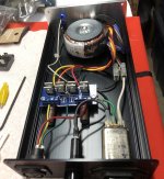
The cases I had on hand were a little too small to run dual power supplies so I decided to just go with a single transformer with dual primary/secondary and rectification.
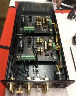
I realized I had a rectifier board lying around from one of Peter Daniels gainclone kits I had built. There is no snubber or caps populated on it.
You don’t call for any filtering, caps or otherwise in your instructions (though I think it is an option with this board). I’ve included a pic showing how I want to use it. Do you see any problems?
I’ve been putting this VSPS 300m kit together over the past week. I’ve got the case for the boards pretty much finished the way I want it.
The cases I had on hand were a little too small to run dual power supplies so I decided to just go with a single transformer with dual primary/secondary and rectification.
I realized I had a rectifier board lying around from one of Peter Daniels gainclone kits I had built. There is no snubber or caps populated on it.
You don’t call for any filtering, caps or otherwise in your instructions (though I think it is an option with this board). I’ve included a pic showing how I want to use it. Do you see any problems?
Attachments
Last edited:
Hi Richard
I’ve been putting this VSPS 300m kit together over the past week. I’ve got the case for the boards pretty much finished the way I want it.
The cases I had on hand were a little too small to run dual power supplies so I decided to just go with a single transformer with dual primary/secondary and rectification.
I realized I had a rectifier board lying around from one of Peter Daniels gainclone kits I had built. There is no snubber or caps populated on it.
You don’t call for any filtering, caps or otherwise in your instructions (though I think it is an option with this board). I’ve included a pic showing how I want to use it. Do you see any problems?
Do you mind sharing where did you get cases?
The cases came from eBay. Sold as power supply cases. They are pretty affordable at about $26 each shipped. Not sure how shipping is going these days out of China.
Power supply Amplifier Chassis / DIY Aluminum Case /size 248*134*55mm | eBay
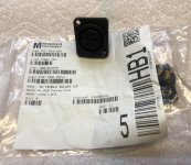
They come with a cheesey power inlet/switch assembly that doesn’t have a third grounding prong similar to laptop bricks. I didn’t use it.
Instead, I mounted my Nuetrik connectors where they machined the case for that inlet. It was almost a perfect match in dimensions. I just had to get creative with the mounting hardware holding it in place. I attached a pic of Mouser bag with P/N and socket.
I have a small milling machine, so I just machined proper size holes for my IEC inlet, fuse holder, RCA and etc.
Power supply Amplifier Chassis / DIY Aluminum Case /size 248*134*55mm | eBay
They come with a cheesey power inlet/switch assembly that doesn’t have a third grounding prong similar to laptop bricks. I didn’t use it.
Instead, I mounted my Nuetrik connectors where they machined the case for that inlet. It was almost a perfect match in dimensions. I just had to get creative with the mounting hardware holding it in place. I attached a pic of Mouser bag with P/N and socket.
I have a small milling machine, so I just machined proper size holes for my IEC inlet, fuse holder, RCA and etc.
Attachments
Hi all, me again, feeling very sheepish as I totally missed the calculator in the BOM spreadsheet...
Long story short I'm comfortable with using that to calculate a reasonable value for R2 for my AT-OC9/III.
Sorry for the unnecessary noise. And thanks to Richard for making these wonderful designs available!
Long story short I'm comfortable with using that to calculate a reasonable value for R2 for my AT-OC9/III.
Sorry for the unnecessary noise. And thanks to Richard for making these wonderful designs available!
Hi Richard
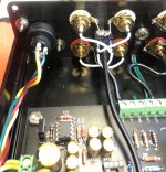
Thanks very much for the kind words. It was much easier to wire the selector switch right between the inputs as opposed to mounting the switch on the front panel as I did on my last phono amp.
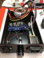
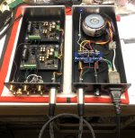
Things have been a bit hectic with everyone being in the house 24/7. I ended up staying up until 3AM last night so I could finish assembling my power supply.
A quick test across my rails told me I had about 38V DC. It’s a little high, but when I tested my mains voltage at the IEC inlet it was slightly over 120V AC. I know there are fluctuations in the mains throughout the day anywhere from 5 to 10V. I’m thinking it was just at a high point at that time of night.
I’m going to try and build my umbilical later today. Then I can test voltages on the amp boards and hopefully pop in IC1 and give it a try in my system.
Thanks very much for the kind words. It was much easier to wire the selector switch right between the inputs as opposed to mounting the switch on the front panel as I did on my last phono amp.
Things have been a bit hectic with everyone being in the house 24/7. I ended up staying up until 3AM last night so I could finish assembling my power supply.
A quick test across my rails told me I had about 38V DC. It’s a little high, but when I tested my mains voltage at the IEC inlet it was slightly over 120V AC. I know there are fluctuations in the mains throughout the day anywhere from 5 to 10V. I’m thinking it was just at a high point at that time of night.
I’m going to try and build my umbilical later today. Then I can test voltages on the amp boards and hopefully pop in IC1 and give it a try in my system.
Attachments
It's clear from the photo you know what you're doing. 38 V is ok, it's unloaded and you have capacitors at the rectifier output. 30-40V range is fine.
By the way you may find it sounds better when you remove those electrolytic caps on the rectifier board. The phono boards already have sufficient filter capacitance, and for some reason splitting the capacitance near/far from the amp introduces some weirdness, sonically speaking.
By the way you may find it sounds better when you remove those electrolytic caps on the rectifier board. The phono boards already have sufficient filter capacitance, and for some reason splitting the capacitance near/far from the amp introduces some weirdness, sonically speaking.
Hi Richard
Thanks for your comments again.
I wasn’t sure if I should include any additional capacitance at the supply or not.
I’ve read more than once in the past that when separating a power supply from a sensitive circuit with an umbilical that it was a good idea to have some capacitance in the supply case and at the circuit.
This rectifier board had the option of adding a snubber which would have resulted in having much larger caps at the supply which I decided against.
As it is, there is only a small 35V Silmic 100uf on each rail. One leg can be easily lifted to test the supply without them.
I finished the umbilical this afternoon and moved on to firing the amp board up and testing my voltages in the circuit.
I’m very glad you were able to send me the original instructions and that I followed all of your start up advice.
I immediately found an issue when I went to test for -10V at pin 4 of the IC1 socket on the first board. There was no voltage.
After rechecking the data sheet for the opa27 and your circuit board diagram in the manual I realized that the original owner of these boards had populated the IC1 socket with its notch reversed to the diagram. I wasn’t testing at pin 4, I was testing at pin 8.
I didn’t really want to have to take the board out and de-solder an 8 pin socket...especially since I recently ran out of soldering wick.
I noticed there was no “key” preventing the op amp from being inserted in the socket with the correct circuit orientation. I simply filled the original notch at the wrong end with some liquid tape and put a notch on the correct end of the socket for my own reference and peace of mind in case I were to ever go back in thinking of trying any different op amps.
After that everything went pretty smoothly. Getting those little bugs into their sockets was a bit of a pain. I have big clumsy fingers and no tool to hold them properly. The legs started to bend on one, then it jumped out of my hands and onto the floor while trying to straighten it out. I don’t think it got damaged as I retested everything once they were installed and all seemed OK.
I didn’t have time to switch the amp into my system today...too much going on. Hopefully tomorrow I will be able to listen to it.
Attachments
Looks good. And no, there is no insertion key for DIP packages, nor transistors for that matter, nor ... if you think about it, any polar two terminal devices like diodes or electrolytic capacitors. It's on the builder to align the component to match the pattern on the silk screen.
- Home
- Source & Line
- Analogue Source
- The Phonoclone and VSPS PCB Help Desk