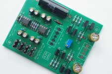
If you are doing your own layout, you can choose however you want. I usually bypass with 0.1 uF on the V+ and V- of each op amp, with some additional electrolytics 100-330 uF total per pin. Here it's 2x100uF, but that's really because it was convenient for the space left on the board. You can use more small capacitors, or one big one, as you like.
Attachments
replaced r2 with 681R - spot on with gain with my dl-103- I'm in love with performance of this preamplifier")
Hi Bolec,
Happy it’s working now. I know it’s subjective, however I’m very curious if you could describe what you like so much about the performance in comparison with the other phono-amp you used.
Also would you be ok to share the rest of your setup/equipment?
I’m considering to build this amp specifically because of the inputstage.
I’m using a Benz-Micro Ace Low output MC, recordplayer is Thorens TD-2001
Currently using an old and very good Mitsubishi pre-amp DA-P10 as phonoamp with stepup coils from Ortofon.
Unison Research simply 2 tube amp with Sonus Faber Electa I speakers
Thank you
I have it on my Rega RP8/Aphetta and it is brilliant.
My thoughts - it sounds clean but not bright. I was very surprised I was not sure what to expect.
I have not run my Rega with any other phono preamp. My Linn LP12 had a IITOK and Troika with a Linn preamp and the Rega/Phonoclone kills it with imaging, warmth, detail and Bass.
My thoughts - it sounds clean but not bright. I was very surprised I was not sure what to expect.
I have not run my Rega with any other phono preamp. My Linn LP12 had a IITOK and Troika with a Linn preamp and the Rega/Phonoclone kills it with imaging, warmth, detail and Bass.
Last edited:
I have it on my Rega RP8/Aphetta and it is brilliant.
My thoughts - it sounds clean but not bright. I was very surprised I was not sure what to expect.
I have not run my Rega with any other phono preamp. My Linn LP12 had a IITOK and Troika with a Linn preamp and the Rega/Phonoclone kills it with imaging, warmth, detail and Bass.
Thank you for your impressions Warrjon.
That sounds very good and promising.
My Thorens is somewhat the same as your LP12 so it might be a good comparison.
Hi all,
I have start building the PCBs.
My original Mouser order didnt have all the Caps so Ill make an order from hificollective.
C3 is the crucial one (from the build info) but I wanted to ask if others used different ones.
1) So my question is: which 2.2u should I choose from hificollective?
2) Any other alternatives from the remaining?
3) Are Elna Silmic II Electrolytic a better option than Nichicon KZ?
Attachments
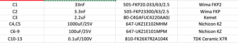
Realistically, there are any number of good options for C3. The value can be 1-3.3 uF, 2.2 uF is just a center point estimate, and there are no particular restrictions for voltage. So it comes down to taste, size, and price. Suggest looking at Mundorf or Audyn.
KZ (Muse) are pretty good, debating which is better, them or Silmic, seems rather futile in my opinion. It doesn't matter.
I would use the BOM parts for C1, C2 simply because the Wima models fit nicely on the boards.
KZ (Muse) are pretty good, debating which is better, them or Silmic, seems rather futile in my opinion. It doesn't matter.
I would use the BOM parts for C1, C2 simply because the Wima models fit nicely on the boards.
Realistically, there are any number of good options for C3. The value can be 1-3.3 uF, 2.2 uF is just a center point estimate, and there are no particular restrictions for voltage. So it comes down to taste, size, and price. Suggest looking at Mundorf or Audyn.
KZ (Muse) are pretty good, debating which is better, them or Silmic, seems rather futile in my opinion. It doesn't matter.
I would use the BOM parts for C1, C2 simply because the Wima models fit nicely on the boards.
Yes the Wima are good and fit. I Can find the Silmic in stock at the moment so Ill go with that and check the 2 C3 brands that you said.
I've seen one in your "G+" photos I remember. Its a 22GBP upgrade (per cap) heheh
thanks!
EDIT: my mistake. the "2.2uF 160Vdc Audyn Cap KP SN" is 10GBP, I was looking at a 250V one.
PS: from my previous Qs, I think Ill go for the hammont chassis boxes with covers (or perforated cover) looks better for my overall design. I hope the 'shielding" is ok with you (based on you last recommendation)?!
Last edited:
I'm getting ready to build the Emerald phono stage with the Switchboard in front. I am struggling with the whole load concept and how to adjust it on the Emerald.
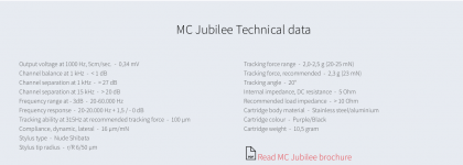
The Ortofon Jubilee and the more recent Cadenza line of cartridges I like are supposed to be loaded at >10 ohms and I have found that 100 ohms sound good to me. This is using a K&K Maxxed-Out phono stage.
I am not sure how to set this value (or make it adjustable) on the Emerald which seems to b have an intrinsic load of 47K.
Also, I can't seem to get the Excel calculator to work. I can't seem to find where to input the specs.
Sorry for the newbie questions but help would be appreciated.
Thanks in advance
Attachments
To use the Switchboard, set the Emerald load jumper open so the load is 47kohms. The Switchboard optionally introduces resistance and capacitance values in parallel to that 47 kohms. The Switchboard in the default BOM gives 1k, 221, 100, 68 and 22.1 ohms, as well as +100pF or +200pF by setting the DIP switches as follows,
(1-4 all OFF) - 47 kohms.
-------
1 ON | 1k
2 ON | 221 ohms
3 ON | 100 ohms
2 and 3 ON | 68 ohms
4 ON | 22.1 ohms
-------
(5-6 both OFF) | 0 pF (+ cable)
5 ON | 100 pF (+ cable)
5 and 6 ON | 200 pF (+ cable)
-------
The data entry fields in the Emerald "Worksheet" are the bold, red numbers next to R1~5. If you change those resistances, the gain and load values change as shown to the right of the input fields. The numbers lower down that page give various examples, but are not calculations and have no user input.
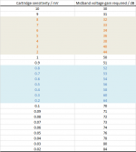
(PS There is no calculator like there is for the Phonoclone. The "cartridge gain" sheet in the BOM gives a list of suggested gain settings for the cartridge sensitivity. There is no user input, just look up your cartridge sensitivity in the list and read off the gain. Your cart is 0.34 mV so the standard Emerald BOM "MC" setting will be fine as is, or you can use option"C" for R3,4 shown in the worksheet.)
(1-4 all OFF) - 47 kohms.
-------
1 ON | 1k
2 ON | 221 ohms
3 ON | 100 ohms
2 and 3 ON | 68 ohms
4 ON | 22.1 ohms
-------
(5-6 both OFF) | 0 pF (+ cable)
5 ON | 100 pF (+ cable)
5 and 6 ON | 200 pF (+ cable)
-------
The data entry fields in the Emerald "Worksheet" are the bold, red numbers next to R1~5. If you change those resistances, the gain and load values change as shown to the right of the input fields. The numbers lower down that page give various examples, but are not calculations and have no user input.
(PS There is no calculator like there is for the Phonoclone. The "cartridge gain" sheet in the BOM gives a list of suggested gain settings for the cartridge sensitivity. There is no user input, just look up your cartridge sensitivity in the list and read off the gain. Your cart is 0.34 mV so the standard Emerald BOM "MC" setting will be fine as is, or you can use option"C" for R3,4 shown in the worksheet.)
Last edited:
Hi,
The default BOM is for the 39db gain (MM) it seems, btw some areas in the excel say 37 but I believe its not updated.
Is it ok if we give a bit more gain than the cart needs?
For example: Is there a design limitation that there isn't enough voltage swing and clips if you add a couple more db than the cart specs? so in essence have a bit stronger output. (Amp input will happily take it).
Thanks (might be a very stupid or elementary question! Sorry)
EDIT: line-ins on my Denon seem to like a bit more input voltage. 4mV with 39db gain gets me to 350-ish mV. I have another cart that only gives me 1.5mV.
Last edited:
@daemonsgr
While headroom is difficult to quantify with any kind of precision, increasing the gain up to 6 dB above the recommended value given in the table below is unlikely to give serious problems with the performance of the the Emerald circuit.
While headroom is difficult to quantify with any kind of precision, increasing the gain up to 6 dB above the recommended value given in the table below is unlikely to give serious problems with the performance of the the Emerald circuit.
Attachments
@daemonsgr
While headroom is difficult to quantify with any kind of precision, increasing the gain up to 6 dB above the recommended value given in the table below is unlikely to give serious problems with the performance of the the Emerald circuit.
thanks a lot,
Ill probably do the default for now (Ive got the parts) and see if I need something like 3 db later.
What's the difference between this power transformer and the one you recommend? Besides ~$40. Is it a suitable replacement?
What's the difference between this power transformer and the one you recommend? Besides ~$40. Is it a suitable replacement?
I'll take "It's not a toroid transformer." for $400 please, Alex.
Sarcasm aside, it'll work as any transformer must. You may have problems with the leakage flux of the unshielded, EI laminate design, you may not. I can't say as I haven't tried. As an external power supply in a separate metal box I imagine it will have no issues.
Hi all,
Im half way there (drilling and finalising is at least the 50% )
A couple of questions:
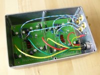
Can I put all inputs, outputs and power XLR all at the back?
XLR in the middle (lower than mid horizon) and in/out left and right.
As you can see my box is a bit tight and I pushed the boards towards the front to leave space at the back.
Will I get interference?
Im half way there (drilling and finalising is at least the 50%
)A couple of questions:
Can I put all inputs, outputs and power XLR all at the back?
XLR in the middle (lower than mid horizon) and in/out left and right.
As you can see my box is a bit tight and I pushed the boards towards the front to leave space at the back.
Will I get interference?
Attachments
@daemonsgr
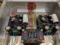
Your case is too small. Even if you get it all hooked up and working, it will cause you much pain and grief. Trust me. Been there, done that.
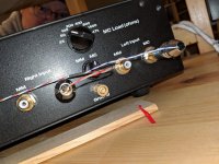
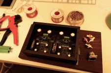
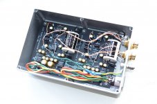
What I recommend though is to mount the XLR and RCA on the side face of the case as you have it pictured, rather than the back. The XLR goes on near the filter caps, the input RCA furthest away, and the output RCA next to the input, with the ground lug about middle.
See attached photos for various photos of builds in my bad old days before I started using reasonable sized cases.
The important point is to route the input wires well away from anything resembling unregulated power, while keeping the input wires as short as possible.
Your case is too small. Even if you get it all hooked up and working, it will cause you much pain and grief. Trust me. Been there, done that.
What I recommend though is to mount the XLR and RCA on the side face of the case as you have it pictured, rather than the back. The XLR goes on near the filter caps, the input RCA furthest away, and the output RCA next to the input, with the ground lug about middle.
See attached photos for various photos of builds in my bad old days before I started using reasonable sized cases.
The important point is to route the input wires well away from anything resembling unregulated power, while keeping the input wires as short as possible.
Attachments
For the first time in ages the VSPS web page has been given an update.
The decision to remove the Allen Wright time constant has been propagated back to the project page, so the boards and the project circuits are consistent again.
The decision to remove the Allen Wright time constant has been propagated back to the project page, so the boards and the project circuits are consistent again.
Hi all,
Im half way there (drilling and finalising is at least the 50%
A couple of questions:
Can I put all inputs, outputs and power XLR all at the back?
XLR in the middle (lower than mid horizon) and in/out left and right.
As you can see my box is a bit tight and I pushed the boards towards the front to leave space at the back.
Will I get interference?
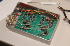
I have to agree with Richard. Your case seems way too small. Not that you can't cram all the stuff in there but you are making it tough to keep stray signals from influencing desired signals.
My last build with no wire twisting or extra shielding is as quiet as can be. Wires are spaced away from each other both horizontally and vertically. Worked far better than anticipated. Case is 11" x 9" x 2 1/4".
Attachments
- Home
- Source & Line
- Analogue Source
- The Phonoclone and VSPS PCB Help Desk