Increase R8 from 47 ohms to 4k7 ohms and then add a switch to connect OUT+ of R and L channels together.
The price you pay is slightly higher output impedance (4k7 ohms) even when the MONO switch is open, but there are no free lunches... that's why it's usually implemented in the preamp input section.
Any suggestions as how to do that? I'd be happy to mod the Cary SLP-98 that is on the way.
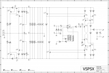
Have a look at the attached schematic. You'd need to insert the 4k7, 470k, and 3.3 uF block into the signal chain, then add S3 (and S4 if you want mute) following.
Thank you Richard. I guess this is beyond the scope of my knowledge level. I'll have to find a good tech in my area to do the mods.

If you have the circuit schematic for the Cary it is probably not too hard to manage as it's all hand wired inside most likely. Since there's already a mute switch it might be that the only thing that needs to be added is another switch for mono/stereo. Maybe. I wouldn't touch it without the service manual though.
Hi RJM. I have been reading the VSPSX post.
I have seen that you have removed the Allen Wright 50 kHz time constant.
I have the VSPS 300 dual mono kit. If I remove the resistor R3 (2k2), will I get any improvement in the sound ?.
I see that the VSPSX tampon is very similar to Marantz HDAM. It fulfills the same purpose ?.
Greetings, Josè
I have seen that you have removed the Allen Wright 50 kHz time constant.
I have the VSPS 300 dual mono kit. If I remove the resistor R3 (2k2), will I get any improvement in the sound ?.
I see that the VSPSX tampon is very similar to Marantz HDAM. It fulfills the same purpose ?.
Greetings, Josè
re. R3: just short over the leads and give it a listen. Really, it shouldn't make much difference at all but I'd like for someone to test it practically.
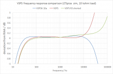
The VSPSX has in addition a low pass filter on the output which means the treble response can be rolled off.
Note the comparison is referenced to the standard RIAA curve. The VSPS is "flat" on the AW modified RIAA curve.
(Yes the buffer circuit is similar to the Marantz version - I didn't copy it from there though, and note the HDAM itself appears to be the discrete op amp module and not the buffer. I'm not totally clear on that though.)
Attachments
Last edited:
Hi RJM!
These last posts have had me thinking, and re-reading what you wrote on the VSPS project's page about the "side effects" R3 has on the impedance of the feedback loop.
As you know I did buffer my stereo VSPS with your excellent bboards, and I am wondering whether I could now safely defeat the AW-correction by shorting across R3... or even better, by installing a switch to disable it at will, depending on the day's mood!?
[what Andrew said]
1m interconnects should be fine, and input stages often don't have an RF filter or if they do have 10k in series with it anyways, so the 2k~ this mod adds to the output impedance shouldn't make much difference.
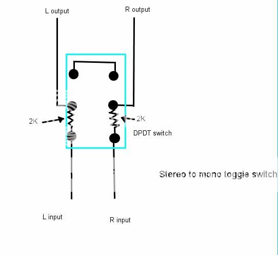
I'm thinking about using this switch/resistor set-up instead of desoldering and resoldering resistors at the board. Thoughts? Does the resistor value make sense in this application? If not, how would one determine appropriate values?
Hello, RJM I have removed the Allen Wright 50 kHz time constant.
Result, sound more pleasant, greater emphasis on bass, a little more midrange. I do not notice any diminution of details.
I think there has been more of the sound, more pleasant.
regards
Result, sound more pleasant, greater emphasis on bass, a little more midrange. I do not notice any diminution of details.
I think there has been more of the sound, more pleasant.
regards
An externally hosted image should be here but it was not working when we last tested it.
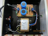
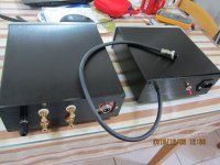
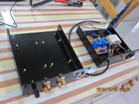
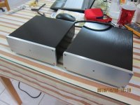
just finished my Phonoclone this morning.
What an amazing sound !
What an amazing sound !
Attachments
Last edited:
And I see you are using my favorite connector for the power umbilical too. Great job, really professional.
Sure I can't interest you in a pair of buffer boards to go with that?
Sure I can't interest you in a pair of buffer boards to go with that?
Why or Why not?
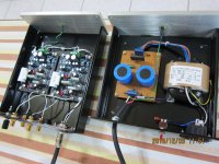
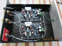
Regarding the build (s) in general, I see some where all the wires both input and output are twisted but the power in wires are not, some where just the power ones are twisted and some where just the inputs/outputs are twisted. Is there a consensus on this? Why or why not to twist?
Regarding the build (s) in general, I see some where all the wires both input and output are twisted but the power in wires are not, some where just the power ones are twisted and some where just the inputs/outputs are twisted. Is there a consensus on this? Why or why not to twist?
Good question.Regarding the build (s) in general, I see some where all the wires both input and output are twisted but the power in wires are not, some where just the power ones are twisted and some where just the inputs/outputs are twisted. Is there a consensus on this? Why or why not to twist?
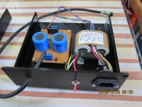
But the glaring error that is Dangerous is the omission of the PE to Chassis Safety connection.
Is there a mains fuse in that IEC input socket?
It is my view that ALL Flow and Return pairs should be twisted to minimise emi.Regarding the build (s) in general, I see some where all the wires both input and output are twisted but the power in wires are not, some where just the power ones are twisted and some where just the inputs/outputs are twisted. Is there a consensus on this? Why or why not to twist?
The umbilical connector looks to be bigger than a 3pin DIN plug and socket.And I see you are using my favorite connector for the power umbilical too. Great job, really professional.
................................
What is it?
- Home
- Source & Line
- Analogue Source
- The Phonoclone and VSPS PCB Help Desk