The problem is not the phonoclone, or LTSpice. Its your transistor design. The impedance of the RIAA network is too high for the circuit to handle causing a massive output DC offset, which in turn is overloading the DC servo.
Try replacing the network values with 1k, 10k, 290nF, 100nF. You won't have enough gain, but the response will now be correct.
Try replacing the network values with 1k, 10k, 290nF, 100nF. You won't have enough gain, but the response will now be correct.
On the bright side you have a really nice 12 dB preamp circuit there. Don't even need the servo, a trim pot will be more than sufficient.
As phono preamp, though, the circuit is basically untenable: the DC input offset voltage is too high. For a MC stage, its useless. No trim pot or DC servo can paper over this fundamental design flaw...
As phono preamp, though, the circuit is basically untenable: the DC input offset voltage is too high. For a MC stage, its useless. No trim pot or DC servo can paper over this fundamental design flaw...
Attachments
Last edited:
I tell you, do not trust simulations ..
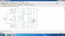
Here's the same phono in another program .. by the way, play for years without any problems ..
You still have not answered the question of how the same RIAA network in two preamp gives a different curve..
edit. Can not upload .tsc file
Here's the same phono in another program .. by the way, play for years without any problems ..
You still have not answered the question of how the same RIAA network in two preamp gives a different curve..
edit. Can not upload .tsc file
Attachments
Last edited:
Sounds nice - especially the Al Stewart recording - nice and open, though there is some sibilance on the vocals (but this is due to the cart - not the phonoclone
") )
)@wirehead.be
I think that's the recording. That song is recorded very "hot" and sibilance is unusually prominant. But yes, the DL103 is has a slightly hard treble. It plays better in the midrange.
@vulejov
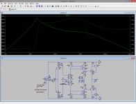
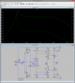
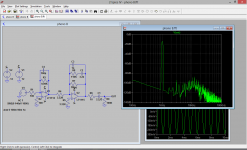
Since your circuit is not linear before you apply the RIAA filter it will not give the correct RIAA response with the standard RIAA network. I mean, just look at the sim below, your circuit with the RIAA removed should give a flat response. Instead, it is +13 dB peak at 20 Hz, almost -3 dB at 20 kHz! To avoid this, you must reduce the "closed loop" gain by lowering the impedance of the network (R12) down to about 10 kohms.
Once you get a linear circuit to start with, you will observe that adding the standard RIAA network (with appropriate impedance) will generate the same response as the phonoclone.
I think that's the recording. That song is recorded very "hot" and sibilance is unusually prominant. But yes, the DL103 is has a slightly hard treble. It plays better in the midrange.
@vulejov
Since your circuit is not linear before you apply the RIAA filter it will not give the correct RIAA response with the standard RIAA network. I mean, just look at the sim below, your circuit with the RIAA removed should give a flat response. Instead, it is +13 dB peak at 20 Hz, almost -3 dB at 20 kHz! To avoid this, you must reduce the "closed loop" gain by lowering the impedance of the network (R12) down to about 10 kohms.
Once you get a linear circuit to start with, you will observe that adding the standard RIAA network (with appropriate impedance) will generate the same response as the phonoclone.
Attachments
Last edited:
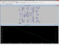
PS. Vulejov, your second simulation has a different circuit than the first. R25/26 R24/25, the 10k and 100 ohm resistors on the output of the servo are reversed, and there are two additional capacitors near T15, T16. The capacitors don't do much, but the resistor order is very important. The servo doesn't overload now.
Ah, at last I see clearly what is going on! That was way more complicated than it ever needed to be.
Vulejov's LTSpice file had an error. Once I fixed that, what he was saying and what I was saying actually started to add up.
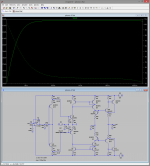
With the circuit error (R25 connected to wrong side of R26) fixed, the circuit now behaves at the high gains. It is running too close to open loop to be ideal but the DC servo can now at least do its job without overloading.
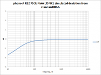
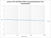
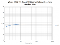
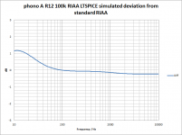
This allows us to settle the RIAA network question once and for all.
Basic issue: The impedance of the node between R14 an R15 is about 4 Mohms. That impedance is in parallel with the RIAA network, so R12 has to be increased slightly from 750k to 1 Mohm to compensate otherwise the bass response is too low. If you bring the impedance of the RIAA network down by a factor of 10 (Cx10, R/10), the 4 Mohms of the node itself is no longer so important and R12 = 75k gives the expected result.
Vulejov's LTSpice file had an error. Once I fixed that, what he was saying and what I was saying actually started to add up.
With the circuit error (R25 connected to wrong side of R26) fixed, the circuit now behaves at the high gains. It is running too close to open loop to be ideal but the DC servo can now at least do its job without overloading.
This allows us to settle the RIAA network question once and for all.
Basic issue: The impedance of the node between R14 an R15 is about 4 Mohms. That impedance is in parallel with the RIAA network, so R12 has to be increased slightly from 750k to 1 Mohm to compensate otherwise the bass response is too low. If you bring the impedance of the RIAA network down by a factor of 10 (Cx10, R/10), the 4 Mohms of the node itself is no longer so important and R12 = 75k gives the expected result.
Attachments

Last edited:
Vulejov's LTSpice file had an error. Once I fixed that, what he was saying and what I was saying actually started to add up.
OK, let's say that you had 75 percent and 25 percent I'm right..
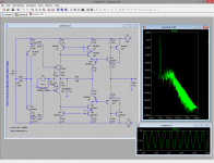
What about FFT analysis, do you think it is correct?
Attachments
OK, let's say that you had 75 percent and 25 percent I'm right..
I think I can live with that.
I wouldn't put a lot of trust in an simulation FFT. Fundamentally they underestimate, since real world behavior is less than ideal. And the result can be completely incorrect if the either sampling frequency or number of data points is insufficient, or the simulation is not allowed to reach steady state before starting to sample the data.
What are the plots from? If you post the circuit, once again I can try to replicate your results.
What are the plots from? If you post the circuit, once again I can try to replicate your results.
I post them already, phono A and phono B..
Perhaps you are thinking of the conventional RIAA network where the resistor and capacitor are connected as (R1||C1)+(R2||C2) and R1~10xR2. (see the input inverse-RIAA I'm using in the sims below for an example) In the VSPS/Phonoclone it is R1||C1||(R2+C2). The ratio of the resistance values are different.
RIAA network in phono A and phono B are same type, which equation should be used?
Basic issue: The impedance of the node between R14 an R15 is about 4 Mohms. That impedance is in parallel with the RIAA network, so R12 has to be increased slightly from 750k to 1 Mohm to compensate otherwise the bass response is too low. If you bring the impedance of the RIAA network down by a factor of 10 (Cx10, R/10), the 4 Mohms of the node itself is no longer so important and R12 = 75k gives the expected result.
4M is parallel with bass resistor..
With ten times smaller resistor bass should be +18 dB, not +21 dB?
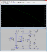
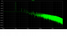
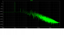
You wouldn't expect the LT1115 to have so much distortion at such small signal levels, and into a 100k resistive load. When I re-did it (see below) I get a more realistic result, though I couldn't say if it is definitively correct or not.
The "phonoclone type" RIAA filter impedance is Z=R1||C1||(R2+C2). If the external circuit parallel impedance (call it Zex) is significant is works out as Z=Zex||R1||C1||(R2+C2).
/R
The "phonoclone type" RIAA filter impedance is Z=R1||C1||(R2+C2). If the external circuit parallel impedance (call it Zex) is significant is works out as Z=Zex||R1||C1||(R2+C2).
/R
Attachments
You wouldn't expect the LT1115 to have so much distortion at such small signal levels, and into a 100k resistive load. When I re-did it (see below) I get a more realistic result, though I couldn't say if it is definitively correct or not.
OK, but I expect less distorsion in phono A then phono B..
I think is more realistic that harmonics are on -60 dB level, that is about 0.001%..
The "phonoclone type" RIAA filter impedance is Z=R1||C1||(R2+C2). If the external circuit parallel impedance (call it Zex) is significant is works out as Z=Zex||R1||C1||(R2+C2).
Same equation in phono A and phono B?
How to add resistance to capacity, and what is what in LTSpice model?
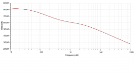
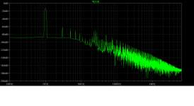
On a lighter note - a practical example of the VSPS frequency response. Actual measurements, no simulations for a change
Input: a 0 to 20kHz tone; with inverse RIAA - Output: the VSPS. Data above 20kHz may be ignored (quite clear from where you can ignore the data ). Pretty linear!
Input: a 0 to 20kHz tone; with inverse RIAA - Output: the VSPS. Data above 20kHz may be ignored (quite clear from where you can ignore the data
). Pretty linear!An externally hosted image should be here but it was not working when we last tested it.
I think is more realistic that harmonics are on -60 dB level, that is about 0.001%..
-60 dB from the fundamental is 0.1%.
-60 dB from the fundamental is 0.1%.
OK, same simulation..
Attachments
On a lighter note - a practical example of the VSPS frequency response. Actual measurements, no simulations for a change
Input: a 0 to 20kHz tone; with inverse RIAA - Output: the VSPS. Data above 20kHz may be ignored (quite clear from where you can ignore the data
RJM and me totaly agree about curve from 1kHz and up, problem is between 20 and 200 Hz, you did not record it?
I'll try to do the same measurement this evening - and if possible with a referenced signal on a logarithmic scale. I'll check what program I can use for the plot - as Audacity isn't that advanced
Vulejov; the tone went from 0 to 20kHz. However; the card used to generate the tone into the VSPS was my on-board Macbook Pro card. Not the best thing for this (and I seriously doubt the card is capable of generating 1Hz tones - or anything below and around 20..). You need a pretty souped up card to generate those inversed RIAA-tones (in the mV range) into the VSPS. So I'll generate that tone with a E-MU 0404 USB tonight (s/n 117dBA output) and I'll record the line signal with my Edirol FA101 (s/n 102dBA). That should give a nice representation.
Vulejov; the tone went from 0 to 20kHz. However; the card used to generate the tone into the VSPS was my on-board Macbook Pro card. Not the best thing for this (and I seriously doubt the card is capable of generating 1Hz tones - or anything below and around 20..). You need a pretty souped up card to generate those inversed RIAA-tones (in the mV range) into the VSPS. So I'll generate that tone with a E-MU 0404 USB tonight (s/n 117dBA output) and I'll record the line signal with my Edirol FA101 (s/n 102dBA). That should give a nice representation.
- Home
- Source & Line
- Analogue Source
- The Phonoclone and VSPS PCB Help Desk