I doubt LME49713 is stable with 200 ohm Rf. It's a CFA and datasheet recommends 1.2K.
OK, thanks for that. I will investigate.
Instead of criticizing other people's work, why don't you get off your @ss and do a simulation yourself and then show your results? I'm sick and tired of people on this message board taking pot shots at what other people are doing without lifting a finger themselves.
I have tried to simulate the TI recommended circuit in Tina, but the software limitations prevent me from creating a good model of the DAC. Either that, or I'm just not talented enough to do it.
Get off my @ss? I did the arithmetic, what did you do apart from uncritically swallow what you were spoonfed? You call this work?
I must say, I don't feel that such chiding is at all helpful. This is intended as a hobbyist website, not a professional publication resource. Most of us have day jobs (many of which are in engineering, by the way) and have other demands on our time which limit the degree to which we are always able to "sanity check" every technical posting while participating in collaborative exchange.
We have all made the occasional technical oversight, and anyone who may believe they have never done so simply is either wrong or hasn't contributed very much that's creative or innovative. I don't wish to see interesting and creative contributions stifled by concerns of being chided for the occasional technical oversite. I suggest, that the sanity check on DIY contributions, simply due to it's avocational nature, would mostly come from fellow DIY contributors. So, sanity check all you wish, that is constructive. A smug attitude, however, is not constructive.

A hobby means that it doesn't matter that you're wrong? That you push on ahead dismissing any objection out of hand?
You guys are taking a pretty lopsided and partisan view here. jcx had his criticism rejected and sneered at without justification, neither of you leapt to his defence. What's sauce for the goose is sauce for the gander, you know.
I didn't see either of you saying, 'Er, ahem, BTW jcx is right...' No, it's, 'Rah, rah, rah, great creative contribution there, old chep.'
Wishful thinking. Which is not doing anybody any favours.
As for smug, it's the OP who blindly rejects what's being pointed out to him until I force the issue.
If the op amp U1 swings 21ma pp, how the -6.2ma are enough to keep it in class A?
Dont forget that U1 has to feed R4 (570ohm) plus the dac output current.
Think before you say someone is wrong.
In the meantime, how about a word of thanks for preventing you from rushing up a blind alley?
Anyone entering a thread with the purpose of simply mentioning some oversight or error is a welcome factor and would receive the thanks you suggest. However, what does waving a verbal finger in the face of the person being corrected add? We all have feelings, as you so amply demonstrate via your comment. Is it really so much to expect that we demonstrate just a bit of humility and a modicum of consideration when correcting the input of others? I certainly don't think so. Forgive me, but I think you protest too much.
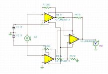
OK, this is where I'm at tonight. I found out that I can't use a bypass capacitor around the feedback resistor for the CFB opamps. Since the minimum feedback resistor is around 1.2K, there is way too much gain, so I had to make a voltage divider with the 5k/1k resistor pairs around the output opamp. This is wasteful but don't know what else to do. Distortion is not that great @ 0.001% with 2.21Vrms out put. Maybe I should just replace the output opamp with a step down transformer...
Attachments
counter culture;3146337 said:I did the arithmetic
If you did the arithmetic. Can you tell us the current swing in U3 output.
I get +1.2mA to –12.3mA and this make U3 work on class b.
The only thing that you have proof until now, is that you have the capacity to make me waste my time.
And please stop saying so many times that I'm wrong, you start to look like my mother in law. And that is very disturbing
OK, I just did a little experiment to find out if the "virtual ground" of the TI circuit with the NE5534 was lower or higher than the same circuit with the CFB LME49713 opamp. Obviously, the value of the feedback resistor plays a big part in how close to zero the "virtual ground" really is. It turns out that with the same feedback resistor of 750 ohms, the LME49713 has half the input impedance of the NE5534 (0.004 vs 0.008 ohms). I don't know if this is a big deal.
Also, with regards to the feedback resistor limitation of the LME49713, I was wondering if it would still work ok with a much lower feedback resistor value if I included a buffer inside the feedback loop. I need to get the gain way down on that stage.
Also, with regards to the feedback resistor limitation of the LME49713, I was wondering if it would still work ok with a much lower feedback resistor value if I included a buffer inside the feedback loop. I need to get the gain way down on that stage.
so I recommended AD810/811/812.
their datasheet have a lot of application information.
Yes you did, and I'm sorry I have not had the time to look at them yet. Thank you, I will when I have time.
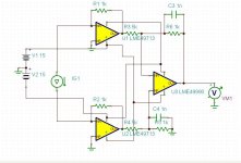
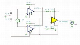
OK, this one works good. It's not stellar, but it's a good performer. Since the AD810 is a video opamp, we have to be careful about layout in the real world.
Thanks for the tip!
For the real world, R3 and R5 need to be changed to 5k to reduce gain, just like the previous example. The good news is that S/N is very good (120dB+) and THD is very good too (0.0002% or so).
But, maybe this isn't any better than the TI circuit.... sigh.
Thanks for the tip!
For the real world, R3 and R5 need to be changed to 5k to reduce gain, just like the previous example. The good news is that S/N is very good (120dB+) and THD is very good too (0.0002% or so).
But, maybe this isn't any better than the TI circuit.... sigh.
Attachments
Last edited:
Dirk, have you ever taken a look at the Twisted Pear IVY circuit? It uses the fully-differential OPA1632 (THS4131).
Yeah, I have looked at that, but they way he draws his schematics is confusing for me. I didn't see any advantage to his circuit except that it offers a balanced output. I don't have the performance numbers either. I suppose I could try to model it and see what I get, when I have time...
I have a note to myself to run an experiment on the PCM1794a chip to see how it performs into different load impedances. There is a website where someone did a little bit of that but not in great detail. I'd like to know, for example, if the distortion output from the DAC changes linearly or exponentially with linear changes in load resistance. If it's linear, then that's bad because then we have to focus on having the absolute lowest possible input impedance for the IV converter. If it's exponential, then it's probably not that sensitive to load impedances (up to the limit of the voltage output of course) and we can use a wider variety of circuits. This is a big unknown. TI specifically says that we have to use their circuit to get their performance numbers, but they are silent on how the DAC responds to changes in load impedance. I think I read somewhere that the engineers who designed this DAC are no longer working at TI so no one knows exactly how it works any more...
Another thing I have not tested is to see how these various circuits perform with out of band signals. Since the DAC puts out a lot of HF junk, then I think it's important to know how the IV converter handles that. This is maybe where the AD810 would have an advantage since it's a video chip. I wonder, for example, if the input impedance changes dramatically with frequency. That would be eye opening...
Last edited:
I've tried an I/V using the OPA1632 with a differential summing stage after it, ie the OPA1632 basically replaced the two opamps following the DAC and it performed horrendously. Yeah it worked, but distortion was through the roof, we're talking at over 1%+. Even if vcom is tied to ground I don't think that automatically sets the input impedance of the OPA1632 to zero.
This was at a time where I was churning out many different PCM1792 PCBs, trying different things/layouts, so it's possible I may have overlooked something in the configuration, but it isn't exactly a complicated circuit.
This was at a time where I was churning out many different PCM1792 PCBs, trying different things/layouts, so it's possible I may have overlooked something in the configuration, but it isn't exactly a complicated circuit.
Thanks for sharing your experience!
I'm surprised it was so bad. It looks like a good opamp. I have not modeled a fully differential opamp yet. I just got the spice model so I'll give it a whirl when I have time.
I'm thinking now that low input impedance is critical for low noise in the IV stage. As for distortion vs. input impedance, the application notes I've been reading basically seem to say that it doesn't matter as long as the maximum voltage at the DAC Iout pins is not exceeded. Then I assume the DAC clips and bad things happen. These were HF video and RF DACs though.
Dirk, have you ever taken a look at the Twisted Pear IVY circuit? It uses the fully-differential OPA1632 (THS4131).
That is a OP amp I have to try . I have already 4 of them. It has high quiescent current .
I have see your Microdac. As I need one. Do you mind that I use your PCB ?
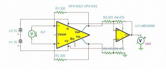
OK, this one measures very well in Tina spice. The inputs to the OPA1632 are not virtual grounds though, since they show 1.56Vrms for a source current of 7.8mA p-p. (it should be in the microvolt range)
But, if the DAC is OK with that, then distortion and noise are very low.
But, if the DAC is OK with that, then distortion and noise are very low.
Attachments
- Status
- This old topic is closed. If you want to reopen this topic, contact a moderator using the "Report Post" button.
- Home
- Source & Line
- Digital Source
- The pcm1794a datasheet I/V converter and how to improve it.