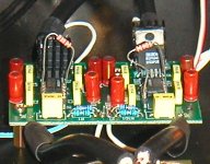
Nuuk said:I may have misunderstood what Joe is saying here but I thought the return wire from the speaker always went to the junction of the two 1000 uF caps anyway (as shown below where the thicker blue wire is the one in question).
[/IMG]
You are right Nick. This is good practice, but more than that, as I'm trying to illustrate. By having those caps right on the chip V+ and V- they now perform an additional task. Look at a lot of amps where big reservoir caps are many inches away. In ALL opamp ICs this becomes much more critical than discrete amps. It has to be because of the internal compensation used by all opamps. The way it's done means that one of the rails have to become a 'ground.' Normal grounding is bad enough, but in opamps... yikes!
The beauty of those 1000uF caps being so close to the 3878 power in pins, they now perform an additional task that normally reservoir caps/electros don't. It greatly simplifies critical opamp grounding. I use Panasonic, many others do as well. Does Sakura/47 Labs use 'naked' Black Gates or something? If they do, these are very good electro caps with good HF performance. Now HF return currents are ably dealt with and no additional components required. On the other hand, if we had remote reservoir caps, we would have to put our thinking caps on (the other kind of cap - or should I say 'hat').
BTW, the 3875 spec sheet shows clearly the internal comp cap has a negative' voltage across it, thus the V- is our pseudo ground, or Clayton's Ground, the ground you have when you don't have a ground.
Or as Forest Gump would have said: Ground is what Ground does.
")
Those internal pics are eye-openers. Gosh, I can imagine what Rod E. would be thinking. The school-master in him would cause him to deeply frown.
"Rip-off."
Now when a large company gets rid of its CEO because of poor performance, and gives him 10 million dollar handshake, that's what I call a real rip-off!

Joe R.
Re: Re: Re: The OPA627 really sings
Can i just put a 1800R resistor across pins 2 and 6 of the opa627 (if i am using +/-15v)?
Rgds
Off topic, but PMA, can this be done using your pcb?PMA said:
OK - I have done it. It does not work for every opamp. But it does work for the OPA627.
My application is the voltage stage in my new amplifier project (error correction amp). The opamp is supplied from +/-18.5V (LM117+LM337). I have chosen the 2.7k resistor from the opamp output to -Vs.
For OPA627, the improvement is substantial. The effect is in clearer mids and highs and the overall resolution for the complex music. The music is more liquid. And the "tail" dissappears. Absolutely positive, nothing to complain. Only very very well designed discrete circuit is capable to give same sound quality as OPA627 with increased Iq.
The biasing against -Vs does not work for AD797 and brings no effect for OPA134.
Can i just put a 1800R resistor across pins 2 and 6 of the opa627 (if i am using +/-15v)?
Rgds
V.,
As you have probably noticed, I have not tried it for audio buffer circuit, but power amp voltage amplifying stage. There is a considerable difference, in audio buffer the opamp is not loaded (high input impedance of the BUF634T) and the opamp output stage class is not an issue that much.
But - there is no technical obstacle to try it. Please feel free to make an experiment and let us know. You do not need to be afraid of any technical problem in your PCB.
Cheers, Pavel
Re: Re: Re: Re: The OPA627 really sings
Make sure you put the resistor across pins 4 and 6, not 2 and 6.
garbage said:
Off topic, but PMA, can this be done using your pcb?
Can i just put a 1800R resistor across pins 2 and 6 of the opa627 (if i am using +/-15v)?
Rgds
Make sure you put the resistor across pins 4 and 6, not 2 and 6.
Re: Re: Re: Re: Re: The OPA627 really sings
Thanks, of course. The resistor must be connected between the output and -Vs.
ABO said:
Make sure you put the resistor across pins 4 and 6, not 2 and 6.
Thanks, of course. The resistor must be connected between the output and -Vs.
I must say that I don't have biasing into class-A on my OPA627+BUF634 pre, because the buffer makes part of the work and I never thought it was necessary, even sonically speaking.
I don't open my pre for a long time, I've been busy with other things.
I will be trying soon other chips and implementations, but completely different from this pre.
If they prove superior, I'll change the pre.
I don't open my pre for a long time, I've been busy with other things.
I will be trying soon other chips and implementations, but completely different from this pre.
If they prove superior, I'll change the pre.
I have finally simulated the whole OPA627 circuitry and can confirm that resistor from output to -Vs changes the mode of operation of the output stage so that only upper transistor works, in SE class A. This is true until load does not suck that much current in negative polarity that lower transistor must open and deliver it. That means that proper value of biasing resistor depends on load resistor, heavier load needs lower value of biasing resistor. But do not overheat the chip.
Slightly OT but can anyone identify this chip for me?
A search on Google doesn't bring anything up. I would guess it is a dual but I found three of them on the output of an old Pioneer CDP.
An externally hosted image should be here but it was not working when we last tested it.
A search on Google doesn't bring anything up. I would guess it is a dual but I found three of them on the output of an old Pioneer CDP.
Experiments with opa627/buf634
Experiments with opa627/buf634:
My opa627 are on sockets, so I was able to plug the 1800R in and out. I A/B it for about 4 times. Cannot really tell the difference.
Diana Krall's voice seemed to be focused with the resistors in. Not too sure. It's not a big impact, maybe very subtle.
I played Temptation from The girl in the other room album.
PMA said:V.,
As you have probably noticed, I have not tried it for audio buffer circuit, but power amp voltage amplifying stage. There is a considerable difference, in audio buffer the opamp is not loaded (high input impedance of the BUF634T) and the opamp output stage class is not an issue that much.
But - there is no technical obstacle to try it. Please feel free to make an experiment and let us know. You do not need to be afraid of any technical problem in your PCB.
Cheers, Pavel
Experiments with opa627/buf634:
My opa627 are on sockets, so I was able to plug the 1800R in and out. I A/B it for about 4 times. Cannot really tell the difference.
Diana Krall's voice seemed to be focused with the resistors in. Not too sure. It's not a big impact, maybe very subtle.
I played Temptation from The girl in the other room album.
Attachments
I changed my mind and switched back to normal operation mode, in the meantime.
Why? Because this chip ist not designed (and evaluated) to be a single ended class a amp. There is to much asymetry and may be the working point of the single output transistor is not optimal.
This is not true class A!
And: they get to hot for my taste.
Franz
Why? Because this chip ist not designed (and evaluated) to be a single ended class a amp. There is to much asymetry and may be the working point of the single output transistor is not optimal.
This is not true class A!
And: they get to hot for my taste.
Franz
Franz G said:
This is not true class A!
And: they get to hot for my taste.
Franz [/QUOTE
The mode of operation depends only on ratio of load resistor and biasing resistor. In case you load it by 10k input impedance of the following amplifier and you use 2.7k resistor from output to -Vs, I can assure you that it is a true class A and that there is no problem with power dissipation. This is not a question of feeling, but circuit technology.
I have good results from around 5 to 10ma biasing and that's what I recommend.
I gave some standard values for the resistor that you can test, at close to 10ma, but you can test other values too.
From 5 to 10ma there's some values you can test.
I wouldn't pass 10ma biasing with the 627.
Franz, what's important is what sounds better for you.
You seam to be biased (no pun intended) by theory.
If unbiased sounds better for you on the circuit you are testing, that's ok, but don't quit at first try.
Biasing an op-amp in class-A in most cases makes it operate in single-ended, I think that it doesn't happen only with the 627.
Another thing: the 627 alone, biased at around 10ma doesn't get hotter than the OPA627+BUF634 in wide BW mode, with +/-18v psu.
It's a little hot, but nothing special.
You can touch it with your finger for the time you want, it's not really hot.
No problems here.
carlosfm said:
Another thing: the 627 alone, biased at around 10ma doesn't get hotter than the OPA627+BUF634 in wide BW mode, with +/-18v psu.
It's a little hot, but nothing special.
You can touch it with your finger for the time you want, it's not really hot.
No problems here.
that is true, i checked the temperature of the opa627 with my fingers with the 1800R resistor (at 8mA plus) . it is only slightly warmer than without the resistor(no heatsink will be required). the buf634 is much hotter in comparison, even with heatsink.
Diana Krall's voice seemed to be focused with the resistors in. Not too sure.
I think you are referring to the album 'The Girl In The Other Room'! But on some of her other recordings, I have found that her voice is not precisely located and I have assumed this is due to her voice being picked up by both her mike and the mike in the piano.

No, really folks: forget about class A, in this case!
It would be nice to have a single ended class A audio opamp, of course. And a single ended class A power opamp.
But you cannot change this chip in a true, balanced class A mode just by bypassing one output transistor!
And the circuit to reduce thermal feedback is out of order.
Please, forget it or like it! But maybe, you cheat yourself?
BTW: the NIGC, reduced caps (removed the 18000uF) and good bypassing seems to be better than an inverted, buffered, regulated version.
I am very sorry! My conclusion: the best buffer is no buffer. Thats the reason, not to use a reversed version, if there is a poti in the input.
Franz
Franz G said:No, really folks: forget about class A, in this case!
People can try, listen and decide.
In some few cases (in some circuits) it may not work so well, but in most cases it sounds better for me.
Are you recommending what sounds better for you?
Franz G said:BTW: the NIGC, reduced caps (removed the 18000uF) and good bypassing seems to be better than an inverted, buffered, regulated version.
Franz, if it works better for you, fine.
How much capacitance per rail are you using now?
Franz G said:I am very sorry!
You don't need to.
Franz G said:No, really folks: forget about class A, in this case!
It would be nice to have a single ended class A audio opamp, of course. And a single ended class A power opamp.
But you cannot change this chip in a true, balanced class A mode just by bypassing one output transistor!
Franz
You should bring any evidence for what you are saying, not only feelings. Me, I can show 2 images.
1st: this is an OPA627 circuit with NFB for gain +10. Rload = 1.6k, R bias = 2.7k.
Attachments
- Status
- This old topic is closed. If you want to reopen this topic, contact a moderator using the "Report Post" button.
- Home
- Amplifiers
- Chip Amps
- The OPA627 really sings