it seems that you based your argument on numbers and thinking that takes the nominal impedance as given, as you had to edit your post after the above numbers for se530 were given. if you had read my posts, you might have picked up that the nominal impedance is pretty arbitrary with this technology and is given at one frequency, often 1khz
anyway i dont want to sidetrack the thread again.
There is no side track here, the performance of the O2 with EIMs is rather important. I don't think of a DAP, Ipod, whatever as a headphone amplifier. They are simply made for $2 earbuds no matter what the marketing division spouts and if that is what you were refering to I understand, case closed.
But a lot of people questioned why RS put the potentiometer after the gain stage for a little better SNR, thinking he was nuts to add this complication. But with IEM's every bit of improvement in SNR especially bellow 200 hz is important. Read RS's latest blog on small signals as pertains to DAC's, some of the same issues crop up with devices like IEM that run on minute amounts of power.
I do see what you mean about the varying impedance of these high end IEM's, but do you think you need to worry about damping factor with those little transducers?
The wildcard is if these high end IEM's (yea fringe
 ) present a significant capacitive load and there is a high frequency dip with output impedance, or a boost in frequency with too low of an output impedance. Or worse the additional pole in the feedback loop with the relatively high bandwidth cause a phase margin/stability issue.
 I don't think thats the case with these EIM's but it seems to be the only implication one can draw by claiming they are hard to drive.
What about the crossover filter in some two or even three-way IEMs? They are usually designed with a certain source impedance in mind. If the IEMs are fed from something with a vastly different impedance than the design impedance, the transfer function of the internal filters is no longer right with consequences for the sound.
There is no side track here, the performance of the O2 with EIMs is rather important. I don't think of a DAP, Ipod, whatever as a headphone amplifier. They are simply made for $2 earbuds no matter what the marketing division spouts and if that is what you were refering to I understand, case closed.
But a lot of people questioned why RS put the potentiometer after the gain stage for a little better SNR, thinking he was nuts to add this complication. But with IEM's every bit of improvement in SNR especially bellow 200 hz is important. Read RS's latest blog on small signals as pertains to DAC's, some of the same issues crop up with devices like IEM that run on minute amounts of power.
I do see what you mean about the varying impedance of these high end IEM's, but do you think you need to worry about damping factor with those little transducers?
The wildcard is if these high end IEM's (yea fringe
I don't think thats the case with these EIM's but it seems to be the only implication one can draw by claiming they are hard to drive.
yawn...whatever you say. oh thats right, not arguing......
multidriver iems fringe? you are showing your age.
like i said, search for posts by jcx, who is imo one of the more worthwhile posters on this forum and HF and he owns jh13, has mentioned them as a rather difficult load for standard headphone amps, not a difficult load full stop, but you need a different tack. did i say the o2 would struggle?, did i say they were an impossible load? no, i said they were a more difficult load than the vast majority of full size dynamic headphones and i stick by that. my guess is you dont own any, havent tried numerous amps with them? more than a guess, i know.
you disregard the ipod as an amp, yet that is the premise i was arguing about, that many people seem to think that just because they are low impedance it must = easy load to drive from anything, but that hd600 are difficult. that is all i said, but now you seem to be moving the goal posts so you can argue some more
its the same thing on a different day with you, repeated in many threads, you argue from 100% theory until someone cuts you down to size, then you go trolling somewhere else
Last edited:
My main concern in mentioning the IEMs is exactly where @regal holds his underlying stance: noise performance of the amp at those load characteristics.
The other SOF's and PoV's add to the conversation in ways.
It seems to me that future measurements at 8Ω of the O2 and other amps are in order. We may also be looking at unity and fractional gain amp builds in the future, the latter having additional resistance that may have certain impacts. Another consideration is the damping factor. My Shure IEMs on my iPod Mini are hard to use wouthout clipping distortion. EQ must be off or I get problems at all volumes. No other earbuds or headphones in my house have that problem. But I never have that problem when listening straight from my PC or TouchPad. I'm not sure what's going on.
So let me ask this: is it better with IEMs to have low output impedance (<1Ω) or high output impedance (>100Ω), and why?
Last edited:
@cusp & @regal, I don't think the two of you are that far apart. All things considered, it's fair to say that many B.A. IEMs place certain demands on the source that many sources fail to deliver--namely sufficiently low output impedance across the entire audio band and/or noise. Distortion performance can also be a factor with some sources.
@timpert, you're correct the impedance curves get even more wild with multi-driver B.A. IEM's and I expect the same is true of the hybrid dynamic/B.A. multi-driver designs. Hopefully Tyll, or someone similarly credible, will publish impedance plots on some of them.
There's a lot of complexity in what a given amp does as the impedance drops. The output devices in the amp (especially in an op amp) have significant Vce saturation voltage that's proportional to the current being delivered. MOS technology ICs or devices have bulk channel resistance that creates a similar proportional drop. Amps often have emitter resistors that create further drop. Darlington outputs have greater Vbe drops that limit their voltage swing. Some amps have significant series resistance in the output but inside the feedback loop (like the Mini3) which limits output and can saturate the feedback loop into low impedance loads. Some amps have output capacitors, Zobel networks, or other non-linear components (even ferrite beads) in their output circuits. Many amps have intentional current limiting and/or Safe Operating Area protection. And, as mentioned, the power supply rails may sag significantly more as the load impedance drops.
All of the above interact in complex ways to not only limit the output in rather unpredictable ways at various load impedances, but also to increase distortion as the load impedance drops. As Regal mentioned, there can also be stability issues with low impedance reactive loads.
The current iPod Touch 4G has an output impedance around 3 ohms which is better than the 7 ohms of the 3G version. It's also reasonably quiet but not hiss free with typical B.A. IEMs. Using the O2 with the LOD line out is significantly quieter in typical use because the volume control is near the end of the signal path and the output stage of the O2 is really quiet.
And even 3 ohms output impedance is enough to cause some potentially audible issues with some B.A. IEMs. My Ultimate Ear Super Fi 5 Pros, for example, are rated at 20-some ohms but dip sharply to around 10 ohms at high frequencies. If you do the math, that might be audible with a 3 ohm output impedance.
To design an ideal (vs merely respectable) amp for B.A. IEMs, and/or ultra low impedance (i.e. < 15 ohm nominal) headphones is tricky. You don't need much voltage swing but you want an amp that's not bothered by really low impedance loads which generally rules out nearly all op amps suitable for high quality audio use. You also, ideally, want low rail voltages and some current limiting to not blow up your $1000 IEMs if someone gets careless. The low voltage headphone "chip amps", like the TPA6102 in the FiiO E7, could be a great solution, but all the ones I know of have rather mediocre audio performance, serious ultrasonic leakage of their charge pumps, etc.
I'll make some O2 measurements into 8 ohms at low voltages. The AKG 125 dB/V means 315 mV RMS would yield an ear splitting 115 dB SPL peak. So I'll run the curves up to 400 mV just to be conservative. That's 70 mA of peak output current at 8 ohms and should be well within the thermal dissipation limits of the paralleled mono NJM4556 even on AC power with +/- 12 volt rails. I know the distortion will look worse than the 15 ohms curves, I just don't know by how much.
Last edited:
isnt noise a given goal for any diy design, i dont consider that anything to argue against or for. well put it this way, after trying all manner of setups with iems over the last 3yrs. i have ended up running just over unity balanced gain from a sabre dac (so ~4vrms), driving directly from either a solid state balanced IV stage (based on opa1632) with the resistors (Zfoil ASMP SMD) lowered for lower voltage noise and the output filter removed, i use this with HD600 as well, or another amp is less than unity balanced gain but buffered with lme49610 is tuned solely for jh13. both use the sabres pot. without the buffer the hd600 is more in its element, the opa dont have a hard time, but the opa1632 (in my case the -power pad package not soic8) can get a little toasty with jh13 (not oscillation, its a known issue, or rather they actually like to run hot, its a bit disconcerting though). the buffered amp turns the jh13 into beasts that beat out the hd600 in all aspects but sound stage width (but not imaging/specificity)
so i dont have problems with noise, output impedance, or the slight midrange suck that can be evident at low volumes with some amps. both amps are running on less than +/-9v with dual mono LDOs only capable of +/-120ma. i cant go much lower without the swing being effected as the op1632 usable swing shrinks considerably into low impedance with a low supply. my needs are too extreme for the datasheet graph, i had to do a lot of experimentation to find the sweet spot
@ ethanolson the ipod EQ is additive, the shures are just more revealing of the clipping thats there the whole time with some material. what music do you listen to? its not the amp being loaded, its being overdriven, while still in the digital domain; its a known weak point of the ipod EQ program.
sorry Regal, i take my troll comment back, when i think about it your particular brand of conversation isnt that far from my own, so maybe its a bit of a pot->kettle thing. but yeah ive done a LOT of research and practical application on this very narrow subject over the last few years as iems are my preferred headphone type even at home.
Last edited:
@ ethanolson the ipod EQ is additive, the shures are just more revealing of the clipping thats there the whole time with some material. what music do you listen to? its not the amp being loaded, its being overdriven, while still in the digital domain; its a known weak point of the ipod EQ program.
I noticed it all over the place on the first few tracks of Water Music... the first non spoken word stuff I put to the IEMs. Additive EQ... must be it! Thanks.
isnt noise a given goal for any diy design, i dont consider that anything to argue against or for.
I can't agree with that. Most DIY headphone amps have the volume control at the inputs and, regardless of what op amps/topology they use, just the Johnson Noise can be audible with IEMs--especially at even modest gains above unity. The same is often true of other resistor values used prior to or in the gain stages.
It's true the Johnson Noise can be at least somewhat reduced by lowering the gain, but not everyone uses their amp only with ultra sensitive IEMs. And not all amps have externally selectable gain. So many need to have more gain to be compatible with other headphones.
And let's not forget many DIYers prefer tubes. Good luck getting less than 6 uV of noise at the output of any tube amp with otherwise decent audio performance.
If you want to consider all the even modestly popular DIY headphone amp designs, I would say most will have audible noise with many B.A. IEMs at even 2.5X gain. And many will have noise at even 1X gain.
And let's not forget many DIYers prefer tubes. Good luck getting less than 6 uV of noise at the output of any tube amp with otherwise decent audio performance.
Should I feel dirty for liking tubes? I'll go scrub my ears now.
I have a bit of channel imbalance with my O2. It is not a lot, but it is certain and not caused by my aging-dependent hearing defects
Anything specific to look at besides the gain resistors?
Cheers,
Nic
Is it a static/fixed imbalance or does it fluctate a little with the volume control (of course it would, but you know what I mean)?
@NicMac do you know about the gain switch clearance issue? The front corner of the switch closest to R21 cannot touch the via pad. If the channels are balanced in one gain mode, but not the other, that's likely the problem.
If that's not the problem I'm guessing there's either a solder bridge somewhere, open connection (not fully soldered part), or you got some resistors mixed up in the wrong locations. The area to look the hardest is everything around U1 and the volume control circuitry including R12 and R13. It's very unlikely there's any problem around U2, U3 or U4.
If that's not the problem I'm guessing there's either a solder bridge somewhere, open connection (not fully soldered part), or you got some resistors mixed up in the wrong locations. The area to look the hardest is everything around U1 and the volume control circuitry including R12 and R13. It's very unlikely there's any problem around U2, U3 or U4.
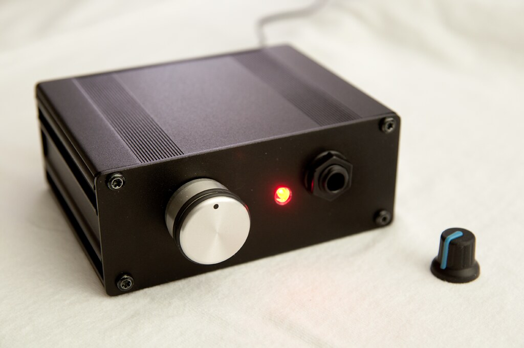
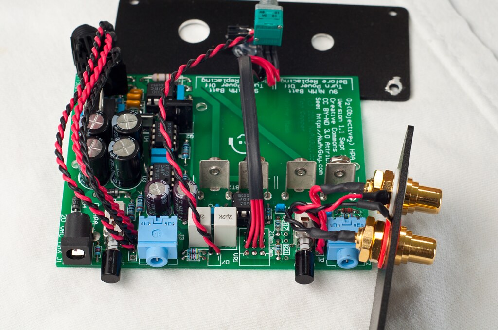
@skkhai, you're welcome. Glad you like it. Very nice wiring and twisted pairs. I also like the volume pot raised up to make room for a big knob.
And, in case anyone is wondering, it's perfectly OK (especially without batteries installed), to leave your O2 plugged in and turned on 24/7 if you have it configured as above with the power switch in the back. The wall transformer won't use much more electricity with the amp on or off and there are no significant issues with component lifespans, etc.
And, in case anyone is wondering, it's perfectly OK (especially without batteries installed), to leave your O2 plugged in and turned on 24/7 if you have it configured as above with the power switch in the back. The wall transformer won't use much more electricity with the amp on or off and there are no significant issues with component lifespans, etc.
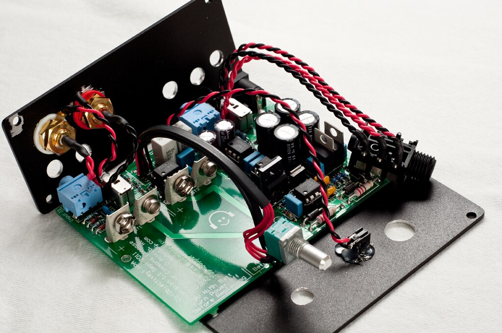
Thanks skkhai for posting this. It's very helpful. How do you know which pads are left, right or ground? I looked at the schematic from nwavguy and concluded that 1,2 are ground. I'm thinking 4 is right because it connects to 2 in J3. Is that correct? Is there a standard that I need to educate my self with or is what I've done basically how you figure it out?
It is not the gain switch issue: it is a close fit but there is no contact and the imbalance is gain selection independent.@NicMac do you know about the gain switch clearance issue? The front corner of the switch closest to R21 cannot touch the via pad. If the channels are balanced in one gain mode, but not the other, that's likely the problem.
If that's not the problem I'm guessing there's either a solder bridge somewhere, open connection (not fully soldered part), or you got some resistors mixed up in the wrong locations. The area to look the hardest is everything around U1 and the volume control circuitry including R12 and R13. It's very unlikely there's any problem around U2, U3 or U4.
Switching U3 and U4 makes no difference (problem persist).
I have checked soldering and I cannot find anything not to my satisfaction. R12/13/17/19/21/23 all OK. The only thing I found a bit unexpected (considering I did not look at the schematics) is that R14 and R20 measure 269R in situ even if they are 10k resistors.
I'm running of batteries.
Any ideas would be appreciated
The tip of 3.5mm plugs is the Left channel. So pin 1 of the input P1 is Left, pin 2 is ground, and pin 3 is Right.
For the output P2, pin 3 is Left, pin 4 is Right, and 1 and 2 are ground as you said.
I should label Left and Right on the schematic.
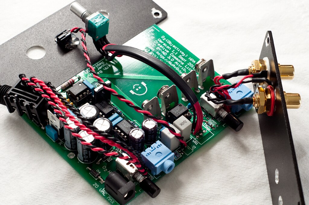
Makes sense. What about VR1. There are 4 rows of 3 pads. I see that he's connecting to the 2nd and 3rd row (ground?) and I'm looking at the JDS on board one, and it's connected to the 1st and 2nd rows.
And let's not forget many DIYers prefer tubes. Good luck getting less than 6 uV of noise at the output of any tube amp with otherwise decent audio performance.
I can't (yet) see what the problem is with tubes. Almost all use an output transformer - so to drive very sensitive IEMs with low impedance, just design in a bigger turns ratio. Transformers are pretty much the only way to get super low-noise at the input (say phono preamps for <5R source resistance) so why wouldn't that also work at the output?
- Home
- Amplifiers
- Headphone Systems
- The Objective2 (O2) Headphone Amp DIY Project