Some good news, I bought the mini jack cable and the o2 amp works perfectly.
Then the problem is the Odac or the conection between them.
Do I cut the traces?, or do you know anything I might try before.
Thanks
EDIT: Just more info, if I connect the Odac to the pc, windows installs the drivers. Then i seect the Odac as default output, if I play some music I can see the green bars moving up and down.
Last edited:
Good to hear that the O2 is OK.
As I mentioned, I've no experience of the ODAC but hopefully someone else can chime in. If not, then it might be worth you starting a new thread here:
Digital Line Level - diyAudio
As I mentioned, I've no experience of the ODAC but hopefully someone else can chime in. If not, then it might be worth you starting a new thread here:
Digital Line Level - diyAudio
I built o2 with odac about 2 years ago and remember I had no sound from one of the 2 outputs. The odac has a line_out and audio_out. Which of the 2 did you use? I can't remember which I ended up using but I do remember that o2 only had sound when I used one of the two. It's probably which ever one is not in the JDS Labs instructions.
Sorry for being a little vague. It's been a while and I can't check my o2 right now. Let me know if you want me to open up my o2 when I have a chance.
Stephane
Sorry for being a little vague. It's been a while and I can't check my o2 right now. Let me know if you want me to open up my o2 when I have a chance.
Stephane
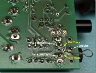
Do I cut the traces?
You do have to cut the traces, even if you are using the O2's P1 connector. NwAvGuy shows where on his blog here, scroll down to the third photo:
NwAvGuy: ODAC May Update
also copied below.
P1 is wired in parallel with the input jack. Those 2 traces short the input jack signal lines to ground when nothing is plugged in, so that you won't hear any hiss. If the traces are not cut they will ground the output of your ODAC (doesn't cause any damage, FWIW) when nothing is plugged into the O2 input jack.
") The exception is if your input jack on the O2 isn't installed at all, then you won't have to cut the traces. The shorting to ground happens with switches inside that jack, via those two traces.
The exception is if your input jack on the O2 isn't installed at all, then you won't have to cut the traces. The shorting to ground happens with switches inside that jack, via those two traces.Attachments
Last edited:
OPA1688
I've been following agdr's OPA1688 cmoy thread and have been planning to build his new cmoy for use at the office. I ordered 2 ea OPA1688 for that project, but instead they ended up in my O2 amp. It started as an experiment, but I'm sure I like the change so I'm going to order 2 more.
I removed the 2 ea NJM4556 and replaced them with 2 ea OPA1688s on DIP8 adapters. No other changes. To my ears it's clearly a sonic improvement. There is more bass, deeper and more solid. There might be a slight mid-range emphasis, I can;t tell about that, I only have one amp and can't switch back and forth quickly. But I do like the low end much better than before.
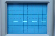
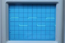
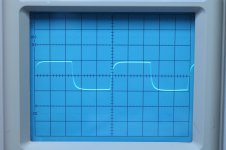
I did take some measurements. DC offset less than 1mV (100uV and 50uV). Square waves at 20KHz, 50KHz, and 100KHz look good, nice and fast, no ringing or other signs of instability (see attached).
Recommended if you would like more bass from your O2 amp.
I've been following agdr's OPA1688 cmoy thread and have been planning to build his new cmoy for use at the office. I ordered 2 ea OPA1688 for that project, but instead they ended up in my O2 amp. It started as an experiment, but I'm sure I like the change so I'm going to order 2 more.
I removed the 2 ea NJM4556 and replaced them with 2 ea OPA1688s on DIP8 adapters. No other changes. To my ears it's clearly a sonic improvement. There is more bass, deeper and more solid. There might be a slight mid-range emphasis, I can;t tell about that, I only have one amp and can't switch back and forth quickly. But I do like the low end much better than before.
I did take some measurements. DC offset less than 1mV (100uV and 50uV). Square waves at 20KHz, 50KHz, and 100KHz look good, nice and fast, no ringing or other signs of instability (see attached).
Recommended if you would like more bass from your O2 amp.
Attachments

I removed the 2 ea NJM4556 and replaced them with 2 ea OPA1688s on DIP8 adapters. No other changes.
Hey you tried it!!
Great work. Very interesting results & square wave tests! Here are my ramblings about this swap to mlackey's good question a few days ago:http://www.diyaudio.com/forums/head...round-headphone-relay-pcbs-4.html#post4842185
I have decided over the years that those NJM4556A's are "the problem" with the O2, especially regarding bass reproduction. Completely subjective on my part, admittedly, which I know would make NwAvGuy bang his head on the table. His detailed objective tests in his blog on the O2 all came out great across the full audio spectrum. But I've heard the difference with a Booster Board replacing those 4556A chips (OPA827 around LME49600 buffers) and something is up there, sonically, that isn't showing up in his measurements for some reason. Probably means there is some other measurement that matters which isn't being done. I have no idea what that would be though.
I'll have to try the OPA1688 swap-out myself!
Something to try: load the output with 470pF and 1nf with both 32R and 150R. It would be interesting to see how much Cload the paralleled OPA1688s on each channel can take before it loses phase margin, without that datasheet 47pF compensation cap. Being in parallel they should be half as sensitive as the single chip case in the OPA1688 datasheet, I would think.
Last edited:
NJM4556A input impedance distortion discussion
I've had a theory for awhile on what the problem with the NJM4556A might be. It is an O2 measurement that NwAvGuy didn't perform. Op-amp input impedance distortion, especially at mid-pot. In the O2 the pot's wiper goes through a 2.2uF coupling cap to the inputs of the NJM4556A chips, with a 40.2K ground return resistor on each input for the input bias current.
When the volume pot is at the high end the NJM4556A inputs see just the 274R RF filter series resistor (266R actually, due to the parallel 10K rest of the pot) plus whatever source impedance exists, usually low.
When the pot is at the other (low volume) end, the wiper is grounded, which grounds one end of the coupling capacitor and essentially puts a 2.2uF capacitor from input to ground on the NJM4556A inputs, in parallel with the 40.2K resistor. The NJM4556A seems to tolerate this, but I've recently discovered the OPA827 doesn't and requires a small resistor between the coupling cap and the op-amp input to prevent the output DC offset from rising slightly (my Booster Board which replaces the NJM4556As).
BUT the interesting case is at mid-pot, where the NJM4556A sees around 2.56K in series with the input. That comes from 1/2 the pot, 5K, on one side of the wiper, in parallel with the other half of the pot in series with the 274R RF resistor on the other side. 2.56K is right in the range that can cause trouble in some op-amps with input impedance distortion and NwAvGuy never posted any THD+N measurements at mid-pot. His distortion measurements were all done at full-pot, which would have minimum input impedance distortion. To find out for certain if the NJM2556A has a distortion problem at mid-pot it would take another round of dScope or AP measurements.
Here are two good white paper summaries of input impedance distortion. The first is an older paper from Linear Technology, now Analog Devices with the August buyout:
http://www.linear.com/docs/4280 (opens PDF)
and here is a recent TI paper done by johnc124 on the forum here!
http://www.ti.com/lit/an/slyt595/slyt595.pdf (opens PDF)
The TI paper discusses a process improvement which significantly lower the input impedance distortion for JFET op-amps. It mentions the OPA1642, but I wouldn't be surprised if the technology also applies to the (FET-input) OPA1688. All of this is why I included "lower input impedance distortion at mid-pot" in that list of potential OPA1688 benefits (vs. the NJM4556A) in my ramblings that I linked to above.
I've had a theory for awhile on what the problem with the NJM4556A might be.
It is an O2 measurement that NwAvGuy didn't perform. Op-amp input impedance distortion, especially at mid-pot. In the O2 the pot's wiper goes through a 2.2uF coupling cap to the inputs of the NJM4556A chips, with a 40.2K ground return resistor on each input for the input bias current.When the volume pot is at the high end the NJM4556A inputs see just the 274R RF filter series resistor (266R actually, due to the parallel 10K rest of the pot) plus whatever source impedance exists, usually low.
When the pot is at the other (low volume) end, the wiper is grounded, which grounds one end of the coupling capacitor and essentially puts a 2.2uF capacitor from input to ground on the NJM4556A inputs, in parallel with the 40.2K resistor. The NJM4556A seems to tolerate this, but I've recently discovered the OPA827 doesn't and requires a small resistor between the coupling cap and the op-amp input to prevent the output DC offset from rising slightly (my Booster Board which replaces the NJM4556As).
BUT the interesting case is at mid-pot, where the NJM4556A sees around 2.56K in series with the input. That comes from 1/2 the pot, 5K, on one side of the wiper, in parallel with the other half of the pot in series with the 274R RF resistor on the other side. 2.56K is right in the range that can cause trouble in some op-amps with input impedance distortion and NwAvGuy never posted any THD+N measurements at mid-pot. His distortion measurements were all done at full-pot, which would have minimum input impedance distortion. To find out for certain if the NJM2556A has a distortion problem at mid-pot it would take another round of dScope or AP measurements.
Here are two good white paper summaries of input impedance distortion. The first is an older paper from Linear Technology, now Analog Devices with the August buyout:
http://www.linear.com/docs/4280 (opens PDF)
and here is a recent TI paper done by johnc124 on the forum here!
http://www.ti.com/lit/an/slyt595/slyt595.pdf (opens PDF)
The TI paper discusses a process improvement which significantly lower the input impedance distortion for JFET op-amps. It mentions the OPA1642, but I wouldn't be surprised if the technology also applies to the (FET-input) OPA1688. All of this is why I included "lower input impedance distortion at mid-pot" in that list of potential OPA1688 benefits (vs. the NJM4556A) in my ramblings that I linked to above.
Last edited:
Let me add:
I did this mod, which is fairly easy to do, the hard part is the precise soldering of the 1688's onto the adapter board/socket. I used my hold in place scotch tape method, get one side soldered, remove the tape and do the other side. Took about 15 minutes total to do this. Be careful to get the PIN 1 in the correct position when you insert back into the O2. (and of course make sure you remove the two 4556's not the other IC's (LOL)).
Mouser Part # 535-LCQT-SOIC8-8, by Aries Electronics. They are $3.03 each.
It cost me $11.55 total with shipping via USPS.
I listening to several songs and they all sound great to me, I will try to do a better listening test later tonight or tomorrow!
All the best
Alex
I have been going back and forth between the O2 Booster board O2 and the 1688 version I just updated and along side a Super Cmoy 1688 version that AGDR designed.
I am a pretty objective guy, and try not to embellish with glittering adjectives how one devices sounds compared to another...after all these are amps, the ole straight wire with gain bit...so if then dont add much to the signal thats a good thing to me, ruler flat over the audio spectrum etc..
That said by subjective side crept in a few times and I thought I could tell differences between these three...even with then matched for amplitude they ALL sound great, or rather neutral to me.
Either of these amps will provide or rather do a great job. If I had to pick out one that I think sounds the best subjectively it would be the 1688 version of the O2....ha!! The easiest and least expensive modification!
I guess to really see if there are any resonse differnences you would need a scope and do some testing as mlackey has done...looks good there.
The good thing is the booster board, the 1688's and the Super Cmoy with 1688s are winners indeed...now where is the Rocket Scientist!! LOL.
Alex
Didn't see this one until now:
If anything, I'd be looking at common-mode distortion, which the sort of buffered VAS used in this part seems to be quite prone to. Old parts also commonly seem to be affected by thermal feedback from output to inputs, an issue eventually addressed by better layout (basically using two pairs of cross-coupled input devices).
Possible but not terribly likely IMHO. The 4556A is not a low-noise part by modern standards, with specified input bias current of 50 nA, which is about as low as acceptable bipolars without any cancellation trickery go. So chances are we're looking at very small input transistors at very low current. Input impedance distortion would be one of my lesser worries there, especially coming from only a 10k pot. Maybe 5532 level. It's never been much of an issue for bipolars anyway, unlike JFET-input parts.I've had a theory for awhile on what the problem with the NJM4556A might be.
If anything, I'd be looking at common-mode distortion, which the sort of buffered VAS used in this part seems to be quite prone to. Old parts also commonly seem to be affected by thermal feedback from output to inputs, an issue eventually addressed by better layout (basically using two pairs of cross-coupled input devices).
Low-noise opamps with low-Rbb' inputs can be quite finicky. Remember how common-emitter circuitry doesn't like inductive source impedance, breaking into oscillation in extreme cases? I'm a bit surprised a medium-noise part like OPA827 would be prone to this though.When the pot is at the other (low volume) end, the wiper is grounded, which grounds one end of the coupling capacitor and essentially puts a 2.2uF capacitor from input to ground on the NJM4556A inputs, in parallel with the 40.2K resistor. The NJM4556A seems to tolerate this, but I've recently discovered the OPA827 doesn't and requires a small resistor between the coupling cap and the op-amp input to prevent the output DC offset from rising slightly (my Booster Board which replaces the NJM4556As).
Alex - very good review! The OPA1688 sub for the NJM4556A that mlackey came up with may have some real mileage. I really like the 1688 so far.
I would be very curious at what point (how much capacitive load) the OPA1688 starts to oscillate, given the "missing" resistor + 1nF capacitor compensation from inverting to non-inverting inputs and "missing" feedback resistor, for the 1x gain case here, to increase phase margin to 50 degrees from 25, that johnc124 came up with in the Super CMOY thread for 1x gain. If someone should try this mod and has the time to test 100pF, 220pF, 470pF, 1nF, and 2.2nF all at either 32R or 150R loads, please post the results!! Somewhere between 100pF and 2.2nF it should start oscillating. I'm guessing it will be somewhere between 100pF and 470pF. Knowing exactly where the oscillations start will really help to understand how useful this mod will be, in general.
sgrossklass - hey thanks for the great analysis! Very interesting. Makes sense about the potential common mode distortion. Good thoughts about what may be going on with the OPA827 there. The OPA827 issue was very repeatable too.
Last edited:
Hey guys I got this question over at another forum:
I really like your mod, but I'm worried about how the OPA1688 will handle output power under 32 ohms or even lower impedance headphones, because despite having the same mA output I see from the datasheet that can only handle 50mW/32ohms before clipping; for 2 paralleled opamp this would be 100mW/32ohms, so about 6 times less power than original 4556 opamps (please correct me if I'm wrong).
I will most likely purchase a couple of OPA1688 opamps soon, because I'm very interested in final results, but meanwhile do you think you could please test output power of your modded O2 with OPA1688 as output buffer for 32ohms output resistance? Also, if you could somehow measure OPA1688 die temperature while doing this test it would be perfect.
I only have used my 250 ohm T90's so far, I will try with lower impedance headphones and a thermocouple today.
Ideas??
Alex
I just placed a thermocouple on the chips, playing for 30 minutes at unity and 2.5x gain with 35 ohm MSR7's headphones, painfully loud levels...way to much for listening...and the temps on the chips got up to 93deg F. (31 deg C).
I dont "hear" any distortion.
Alex
I dont "hear" any distortion.
Alex
Last edited:
93 F is a normal operating temperature. I would guess no oscillation yet. Now try putting a 1nF or 2.2nF across the O2's outputs, with that 35R headphone load still plugged in, and see what that does. You could just tack solder the caps across the O2 output jack under the board.
The goal is to add enough parallel C for the phase margin to drop below 20 degrees or so and start oscillating. You may get 120F - 150F+ when it does.
You could just tack solder the caps across the O2 output jack under the board.The goal is to add enough parallel C for the phase margin to drop below 20 degrees or so and start oscillating. You may get 120F - 150F+ when it does.
Last edited:
I listening to several songs and they all sound great to me, I will try to do a better listening test later tonight or tomorrow!
I am curious to know if you hear more bass, or is it me?
mlackey,
I honestly think they sound really close, I cant tell the difference playing bass heavy or bass articulate recordings. If I level match they sound really close.
I will see if I have a small cap lying around and try that as well, tacking is an easy thing to do for me!! lol!
I have used 250 ohm and 35 ohm headphones.
This morning I went back and forth between the 1688's and the 827 booster board and I keep picking out the booster board as being the one I like better, subjectively it sounds more open and transparent, but that's a subjective guess on my part. If I level match them again, and listen to either one for 5 minutes or longer they both sound great, its the immediate switching is when I think I hear the difference. But its not on the bass end or the high end, just overall presentation.
Alex
- Home
- Amplifiers
- Headphone Systems
- The Objective2 (O2) Headphone Amp DIY Project