Its hard to say what you're hearing (or not) but all I can say is that the O2 is very very good at what it does. It has a very flat resonse and a very low output impedance which means that the 'phones are driven correctly.
You could actually try increasing the value of the 1 ohms output resistors R10/11/15 and 18 and see if that gives you any benefit. You can go as high as you like as long as you still get sufficient volume. Many amplifiers do just use a high value series feed resistor for headphone drive.
You could actually try increasing the value of the 1 ohms output resistors R10/11/15 and 18 and see if that gives you any benefit. You can go as high as you like as long as you still get sufficient volume. Many amplifiers do just use a high value series feed resistor for headphone drive.
Hi guys,
I bought my O2 kit from walter (Head'n'Hifi) in Dec. of 2013 and I enjoyed building it and modding it as well.")
First upgrade/mod was done about 1 year ago when
- I replaced "input source" 3.5mm jack with a "headphones out" 6.3mm Neutrik jack
- I installed an additional back power plug
- I also installed 2xRCA input plugs
- Replaced input OPAMP from NJM2608 to LME49720
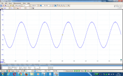
Now, that it just had its 2'nd birthday a couple of weeks ago, I was thinking to make some more upgrades a little bit. While trying to find what's my O2's max. non-clipping output voltage I was able to get a decent gain voltage of 7.4-7.5V RMS and a headphones output voltage of 7.3-7.4V RMS (with dummy load of 500ohms resistors + original Beyers cable serialized, instead of headphones) before starting to clip and without any sort of strange FFT spikes or oscillations.
So, while my 3 years old kid was spilling water inside a power stripe's outlet (thank's God of the 30mA differential safety) I the following "present" to my O2:
- 1) Changed the gain resistors from infinite/1Kohm (corresponding to 1X/2.5X) to 2.5Kohm/516ohms (corresponding to 1.6X/3.78X). I did some "custom resistors" of about 516ohms by serializing 274ohms + 242ohms resistors that I had in stock; this corresponds to a real gain of about 3.78X and an output voltage of about 7.3V RMS when connected to ODAC. Looks like my ODAC can output 1.921V RMS when 0dB sinewaves are applied and connected to O2 with 7.3V RMS on outputs I have tried 20Hz, 32Hz, 1KHz, 16KHz, 20KHz and I get no clipping on O2 output, no roll-offs, no oscillations, no strange FFT harmonics, no THD >0.1% (checked with my PicoScope 2204A).
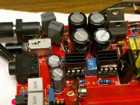
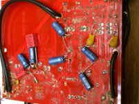
- 2) Added 2 x 1uF film capacitors immediately after the 2 regulating diodes from power input plug. These 2 caps should decrease any possible noise coming from the mains.
- 3) Added 2 x 10uF/25V AVX tantalums on output regulators, to further decrease the already low ripple.
- 4) Added 2 x 47uF/35V Nichicon KA and 2 x WIMA 0.1uF/100V for decoupling the input stage OPAMP (LME49720).
- 5) Added 2 x 47uF/35V Nichicon KA for each of the 2 output buffers for decoupling purposes (NJM4556A).
Did I gained anything?
- Besides a lot of fun, I was able to decrease ripple & noise from 2.3mV p-p to 0.747mV p-p, measured directly on each regulator output and also from OPAMPs +/-V rails to GND. That's a good ripple decrease, though it will probably not be noticed on headphones out, because O2's OPAMPs already have a good ripple reduction inside (PSRR & CMRR of about 90-100dB).
- I feel like soundstage increased a little bit, though this is a subjective impression, but I hope I'm going to test it sometime by A/B'ing, when I'll find another O2 to borrow.
- OPAMPs rolling should be easier now with additional decoupling caps used.
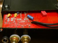
Note: The tested O2 has LME49720 on input stage and 2 x NJM4556A as buffers. All 3 OPAMPs have heatsinks on top, glued with Arctic Alumina compound. There are 2 power plugs in front and back, 2 headphone jack: 3.5mm and 6.3mm on front and RCA outputs on the back. I'm also using original 9V/300mAh batteries and original 15V/500mAh power adapter.
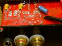
P.S.: Looks like the way I arranged one of tantalums was not good (4'th attach.), because I couldn't close the case, so I need to move it a few mm away from the edge of the PCB (last attach.).
I bought my O2 kit from walter (Head'n'Hifi) in Dec. of 2013 and I enjoyed building it and modding it as well.
First upgrade/mod was done about 1 year ago when
- I replaced "input source" 3.5mm jack with a "headphones out" 6.3mm Neutrik jack
- I installed an additional back power plug
- I also installed 2xRCA input plugs
- Replaced input OPAMP from NJM2608 to LME49720
Now, that it just had its 2'nd birthday a couple of weeks ago, I was thinking to make some more upgrades a little bit. While trying to find what's my O2's max. non-clipping output voltage I was able to get a decent gain voltage of 7.4-7.5V RMS and a headphones output voltage of 7.3-7.4V RMS (with dummy load of 500ohms resistors + original Beyers cable serialized, instead of headphones) before starting to clip and without any sort of strange FFT spikes or oscillations.
So, while my 3 years old kid was spilling water inside a power stripe's outlet (thank's God of the 30mA differential safety) I the following "present" to my O2:
- 1) Changed the gain resistors from infinite/1Kohm (corresponding to 1X/2.5X) to 2.5Kohm/516ohms (corresponding to 1.6X/3.78X). I did some "custom resistors" of about 516ohms by serializing 274ohms + 242ohms resistors that I had in stock; this corresponds to a real gain of about 3.78X and an output voltage of about 7.3V RMS when connected to ODAC. Looks like my ODAC can output 1.921V RMS when 0dB sinewaves are applied and connected to O2 with 7.3V RMS on outputs I have tried 20Hz, 32Hz, 1KHz, 16KHz, 20KHz and I get no clipping on O2 output, no roll-offs, no oscillations, no strange FFT harmonics, no THD >0.1% (checked with my PicoScope 2204A).
- 2) Added 2 x 1uF film capacitors immediately after the 2 regulating diodes from power input plug. These 2 caps should decrease any possible noise coming from the mains.
- 3) Added 2 x 10uF/25V AVX tantalums on output regulators, to further decrease the already low ripple.
- 4) Added 2 x 47uF/35V Nichicon KA and 2 x WIMA 0.1uF/100V for decoupling the input stage OPAMP (LME49720).
- 5) Added 2 x 47uF/35V Nichicon KA for each of the 2 output buffers for decoupling purposes (NJM4556A).
Did I gained anything?
- Besides a lot of fun, I was able to decrease ripple & noise from 2.3mV p-p to 0.747mV p-p, measured directly on each regulator output and also from OPAMPs +/-V rails to GND. That's a good ripple decrease, though it will probably not be noticed on headphones out, because O2's OPAMPs already have a good ripple reduction inside (PSRR & CMRR of about 90-100dB).
- I feel like soundstage increased a little bit, though this is a subjective impression, but I hope I'm going to test it sometime by A/B'ing, when I'll find another O2 to borrow.
- OPAMPs rolling should be easier now with additional decoupling caps used.
Note: The tested O2 has LME49720 on input stage and 2 x NJM4556A as buffers. All 3 OPAMPs have heatsinks on top, glued with Arctic Alumina compound. There are 2 power plugs in front and back, 2 headphone jack: 3.5mm and 6.3mm on front and RCA outputs on the back. I'm also using original 9V/300mAh batteries and original 15V/500mAh power adapter.
P.S.: Looks like the way I arranged one of tantalums was not good (4'th attach.), because I couldn't close the case, so I need to move it a few mm away from the edge of the PCB (last attach.).
Attachments
TBH I would rather prefer to leave 1-2 dB of analog headroom above 0 dBFS in order to account for intersample-overs. Not sure how much headroom the ODAC itself provides, the classic fs/4 90° +3dBFS test tone might tell (have this online somewhere in case you can't find it).
Granted, this is mostly a problem for "bit perfect until the last mile" purists. Throw some digital attenuation in there (and e.g. ReplayGain will dial in plenty on problematic recordings), and it becomes a non-issue.
Heatsinks for the 4556As aren't a bad idea actually, seems like they can blow up when driving 16 ohm loads at high levels.
...
Heatsinks for the 4556As aren't a bad idea actually, seems like they can blow up when driving 16 ohm loads at high levels.
I know what you're saying; I've seen one 4556 blown away on Head-Fi; JDS replaced it for free (if I remember correctly HE400 was the reason for this).
Hiyas. I've started building, 6 resistors are in, looking good enough imo. Doublechecked the values with a multimeter. Sofar so good.
However I'm confused by R9 on the official parts lists. These say it should be !33K Ohm. Afaic, this could mean 33 K Ohm and 133 K Ohm. Which one should it be? Apparently, 133 K Ohm is a standard resistor.
However I'm confused by R9 on the official parts lists. These say it should be !33K Ohm. Afaic, this could mean 33 K Ohm and 133 K Ohm. Which one should it be? Apparently, 133 K Ohm is a standard resistor.
Guys, I have a very weird problem.
My freshly assembled O2 only works in battery mode. When only hooked to the wall wart, it's dead silent. Not even the turn on click and turn off thump can be heard. In battery mode, it works perfectly fine with music and all.
Here are some pics of my build and soldering: Imgur: The most awesome images on the Internet
The kit is from Head n Hifi.

I bought an o2 kit from head n hifi, tried building it, but it seems like I failed and I'd really appreciate some help. I built it and started the testing procedure. I got these wrong resistance measurements with U2 in:
* R5 measures 230k
* R25 measures 390k
* R2 and R1 measure 255
But since those were marked with * and ~ I thought such differences might be fine (I hate myself for this), and went one with further testing. My AC power supply measures about 18V, I plugged it in and measured the voltage at the outermost battery terminals and got 18-19 volts with the switch on as well, which I thought was fine (I hate myself) and tried the next test - putting U2 in and the plugging the power supply in - I measured around 18-19 again, but this time after a bit of time (perhaps because I kept it on longer) the top of the C2 capacitor popped open. It had gotten hot, which I didn't notice. After this I inspected all other elements and didn't notice any heat.
I bought an o2 kit from head n hifi, tried building it, but it seems like I failed ...
It seems like I can't edit my post so I will reply to it.
Turns out I soldered C2 backwards. I don't know how I didn't notice until now. Does that have an effect on the resistance measurements from my post? And what other components could have I damaged by doing this?
Dear All,
I have two questions:
1) I have a 20 VAC transformer that measure 22V open circuit. Will it be a problem to use it with the O2 ?
2) What about feeding it with 19V DC. The PSU of my laptop gives this voltage. It looks like that if I put the + on the center it should work, as after the caps, the circuit does not know if it was fed by DC or AC originally.
Thanks,
Davide
Hi,
I believe 20 VAC should be fine, just double check temperature for both power regulators.
Power Adapters - Objective2 Amplifier Wiki - Wikia might help as well.
Raul.
I believe 20 VAC should be fine, just double check temperature for both power regulators.
Power Adapters - Objective2 Amplifier Wiki - Wikia might help as well.
Raul.
22Vac is going to generate around -/+ 31 volts. You are right up at the safe limits for both the regulator input voltage and the cap voltage rating. As mentioned above... heat dissipation could be an issue, particularly when you start charging discharged batteries.
You can not use a single DC supply to power the O2. It can not be configured to use that without a major redesign.
You can not use a single DC supply to power the O2. It can not be configured to use that without a major redesign.
@Nikon1975
A series resistor between 150-220R (2W or above) would also help in dropping the voltage (by approx 10V) & also help in taming the filter capcitor's (35V max) charging current. 1 each in series with rectifier diodes would also help to keep temperature down.
A series resistor between 150-220R (2W or above) would also help in dropping the voltage (by approx 10V) & also help in taming the filter capcitor's (35V max) charging current. 1 each in series with rectifier diodes would also help to keep temperature down.
Last edited:
I have a few questions about my O2 amp I built which is not working, perhaps someone has encountered the same problem. I am getting a loud distortion sound through headphones when I turn on the amp, my first thought is that it could be because I used a 1.7v red LED instead of the one specified in the BOM (seems to be a discontinued model).
Any thoughts? I've checked and resoldered the connections, checked component orientation and ensured there are no solder bridges, but no luck yet.
Cheers,
Alex
Any thoughts? I've checked and resoldered the connections, checked component orientation and ensured there are no solder bridges, but no luck yet.
Cheers,
Alex
Alex,
you need to work through the fault-finding guide I have put together and that is linked to at the bottom of post #1
The red LED is an unfortunate aspect of this design because it is critical in that it determines the low battery cut off point. Work through the guide paying particular attention to the supply voltages as measured at the opamps and also any DC offsets present (there should none).
- Home
- Amplifiers
- Headphone Systems
- The Objective2 (O2) Headphone Amp DIY Project