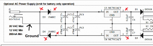
Ground is the point I have marked on the diagram here. So that carries through to the batteries where you have measured from which is fine. Reading from ground to all the points marked with a red cross should not give a 'short circuit reading'.
So the striped end of D3 (that should be the end that goes to C3 and C4) should not read as low as you are getting. That indicates a short which is either caused by something physical (a solder blob) or a faulty reg or a faulty cap (C3/C4).
So the striped end of D3 (that should be the end that goes to C3 and C4) should not read as low as you are getting. That indicates a short which is either caused by something physical (a solder blob) or a faulty reg or a faulty cap (C3/C4).
Attachments
i just double checked again and there really are no visible shorts/solderblobs on either side of the pcb. i also used DMM to look for more shorts like D3. it seems i get the same beep response on several places, like D1(non striped side), c6 and the right side of r12, r13, r17, r21.
are some of these closely connected to ground and should beep?
and how do i know if a cap is faulty (other than seeing if they are blown and swollen)?
Hope I'm not too much of a bother, thanks again for the support!
are some of these closely connected to ground and should beep?
and how do i know if a cap is faulty (other than seeing if they are blown and swollen)?
Hope I'm not too much of a bother, thanks again for the support!
J1 is the DC power jack. That is why you have hum if you connected to the ground there,. There are some really big current spikes moving back and forth between the power jack and the filter capacitors.
The ground ring of the RCA connectors goes to the center (middle of jack, towards the front of the board) pin of J2, the input jack that you connect to your music source. And you should only use one wire, not two, or you risk a ground loop. Just run one wire from that pin on J2 to the ground ring on either RCA jack. The other RCA jack is touching the case with its ground ring, and you just grounded the case with your other RCA jack ground ring and your sanding, like MrSlim said.
If you just made a typo and really are connecting to J2 instead of J1 then the two wires, rather than one, may be the cause of the hum. Also try to route that single ground wire away from the area around the DC jack and 4 filter capacitors C2 - C5 to avoid hum pickup.
Hi All,
noobie here! Just received mine from JDS Labs.
I want to add RCA input so I just follow the above in combo with

(taken from: http://www.diyaudio.com/forums/headphone-systems/236962-building-o2-novices-build-experience.html)
to get my RCA input?
Do you think it'll fit in the standard JDS Labs case?
Otherwise I might have to just drill a small hole and run a dangly cable for it, will that work? As long as I hot glue for some strain relief I guess. Happy soldering!
i just double checked again and there really are no visible shorts/solderblobs on either side of the pcb. i also used DMM to look for more shorts like D3. it seems i get the same beep response on several places, like D1(non striped side), c6 and the right side of r12, r13, r17, r21.
are some of these closely connected to ground and should beep?
and how do i know if a cap is faulty (other than seeing if they are blown and swollen)?
Hope I'm not too much of a bother, thanks again for the support!
Not at all
")
Using a 'beeb' test isn't actually very conclusive in a lot of cases, also using the diode range for checking for shorts can sometimes be misleading.
It could well be easier and quicker to power the unit up with the low voltage bulb tester in circuit and see what voltages appear and what don't. With the 02 power switch off you should get the two 12 volt rails appearing. Lets see what happens.
alright i have my new psu hooked up with the low volt bulb (and its glowing but not much), here's the result:Not at all
Using a 'beeb' test isn't actually very conclusive in a lot of cases, also using the diode range for checking for shorts can sometimes be misleading.
It could well be easier and quicker to power the unit up with the low voltage bulb tester in circuit and see what voltages appear and what don't. With the 02 power switch off you should get the two 12 volt rails appearing. Lets see what happens.
- non-striped end of D3: -6,6
- striped end of D3: 0, no response on DMM
- non-striped end of D4: -18,52
- Striped end of D1: 0, no response on DMM
- non-striped end of D5: -11,87
Hi, noobie here as wellHi All,
noobie here! Just received mine from JDS Labs.
I want to add RCA input so I just follow the above in combo with...
I ordered my O2 parts from Head'n'Headfi and noticed that they have a "desktop kit for O2" with RCA and some other stuff. So it should fit in the case but obviously the panel will not have the right holes if its not made for RCA.
If you are interested they have instructions on how to use the desktop kit.
(and to be clear, i did not buy the desktop kit and have not tried to add RCA input)
Last edited:
Your readings show the minus 12 volt rail is OK. That's D4, U6 and D5. So that looks good to go.
The plus 12 volts is missing but the readings are little odd.
D4 striped end and D3 non striped end should have continuity between them. So check that is OK. I'm assuming D3 is running cold (it should). Check continuity between D3 striped end and pin 1 of the 12 volt regulator.
If all that is OK then D3 looks to be faulty in some way.
Is the "beep-mode" actually continuity-mode? in that case:Your readings show the minus 12 volt rail is OK. That's D4, U6 and D5. So that looks good to go.
The plus 12 volts is missing but the readings are little odd.
D4 striped end and D3 non striped end should have continuity between them. So check that is OK. I'm assuming D3 is running cold (it should). Check continuity between D3 striped end and pin 1 of the 12 volt regulator.
If all that is OK then D3 looks to be faulty in some way.
D4 striped and D3 non striped goes beep.
D3 striped and top pin of U5 goes beep (thats pin 1 of the 12 volt regulator right?).
and i wrote before that the striped end of D1 has no response, but forgot to add that the nonstriped side is the same - 0v.
Beep mode isn't always good enough because it will beep even with significant resistance although I don't think that is the case here. Using the ohms range can be better. You should be seeing essentially 0.00 ohms although the meter leads will add to that by around say 0.3 ohms.
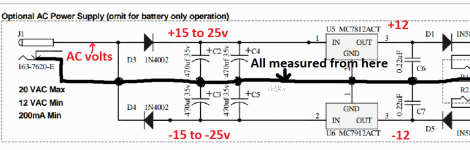
With the black of the meter on ground and the meter set to AC volts you should be seeing the same voltage on D3 (non striped) and D4 (striped). That's proof enough that the AC voltage is reaching the diode. Measure on the diode itself, not on the print because that eliminates any possibility of open circuit print.
If the same AC is present above then you should see around plus 18 volts on the striped end. Measure on the diode itself and remember this time we are measuring DC volts.
If you look at the circuit, then the voltages should mirror each other, -18 at the bottom, plus 18 at the top. Minus 12 volts from the lower reg, plus 12 volts from the upper.
It looks like there is a problem with D3 which is unusual, diodes are tough normally. I think all you can do is replace it to eliminate it at this stage. That doesn't mean there isn't another issue but the diode does at this stage look faulty.
i get the same voltage on both - 005. (supposed to be that low?)With the black of the meter on ground and the meter set to AC volts you should be seeing the same voltage on D3 (non striped) and D4 (striped).
The striped end of D4? actually striped end of D4 gives the same reading as non-striped end of D3: -6,6If the same AC is present above then you should see around plus 18 volts on the striped end. Measure on the diode itself and remember this time we are measuring DC volts.
edit: oh wait you mean striped end of D3 that currently gives no reading should be at +18v right?
Last edited:
i get the same voltage on both - 005. (supposed to be that low?)?
Not exactly that low, but I'm less concerned about that without seeing your meter and how you are using and measuring it. The fact you have -18 volts present means the AC is OK.
The striped end of D4? actually striped end of D4 gives the same reading as non-striped end of D3: -6,6
Look at the circuit. They are one and the same point so they must see the same voltage.
edit: oh wait you mean striped end of D3 that currently gives no reading should be at +18v right?
Yes
And another thought... your readings actually could be because the adapter is not an AC output. Can we be 100% certain on that ? If it were DC then if you swap the input leads around you would find that the plus 12 would now be the correct voltage and the minus 12 would drop to zero.
Just trying to cover all bases
Just trying to cover all bases
I appreciate your concern but it's defenitly an AC output adapterAnd another thought... your readings actually could be because the adapter is not an AC output. Can we be 100% certain on that ? If it were DC then if you swap the input leads around you would find that the plus 12 would now be the correct voltage and the minus 12 would drop to zero.
Just trying to cover all bases
DMM shows output of 16,3v AC but it says 15v on the adapter.
Couldnt find anywhere nearby to buy new diodes for D3, but i found some cheap ones online. downside is that its going to take some time to ship them here, guess i will just have to wait
OK, no problem
There are dozens of suitable common diodes if you could get those locally, any 1amp 50 volt or higher would be suitable.
You could also still test the plus 12 volt section by swapping the two diodes over, well no point putting the suspect one in the other side, but you get the idea. As I mentioned... there may be another problem other than just the diode, so use the bulb tester until its sorted.
swapped the diodes over and the result is the same as before, D3 is still giving strange readingsOK, no problem
There are dozens of suitable common diodes if you could get those locally, any 1amp 50 volt or higher would be suitable.
You could also still test the plus 12 volt section by swapping the two diodes over, well no point putting the suspect one in the other side, but you get the idea. As I mentioned... there may be another problem other than just the diode, so use the bulb tester until its sorted.
the diode that was giving 0v on one side in D3 is now in D4 and it gives the normal 18v reading. guess its not the diode then... any ideas?
guess its not the diode then... any ideas?
Only one based on the evidence so far
Put your meter on DC volts and keep the black meter lead on ground. Now measure the output of the adapter which is the common connection of the two diodes.
Tell me what reading you see and whether there is a plus or minus sign to it. Now reverse the meter leads and tell me what you get.
These diagrams should help explain how it works and allow you to pin down the fault.
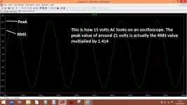
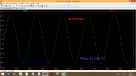
Firstly, you need to understand that 15 volts AC is actually a sine wave that swings above and below a notional zero point. The meter measures what we call the RMS value of the sine but the reality is the sine has peaks that are 1.414 times that value as shown here.
So that is what a 15 volt AC adapter produces.

This is the circuit of the 02 power supply. Look at the points I have marked showing the voltages of Vplus, Vminus and Vac.

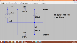
This shows in real time how the circuit works. The top diode conducts as the sine wave goes up and the lower diode conducts when it goes down. Look at the first cycle of the AC and follow how the diodes conduct, and how the DC voltage is then 'held' or stored by the capacitors.

If the adapter were DC then only one of the two rails would appear. Reverse the adapter connection and the rails would swap over.
Firstly, you need to understand that 15 volts AC is actually a sine wave that swings above and below a notional zero point. The meter measures what we call the RMS value of the sine but the reality is the sine has peaks that are 1.414 times that value as shown here.
So that is what a 15 volt AC adapter produces.
This is the circuit of the 02 power supply. Look at the points I have marked showing the voltages of Vplus, Vminus and Vac.
This shows in real time how the circuit works. The top diode conducts as the sine wave goes up and the lower diode conducts when it goes down. Look at the first cycle of the AC and follow how the diodes conduct, and how the DC voltage is then 'held' or stored by the capacitors.
If the adapter were DC then only one of the two rails would appear. Reverse the adapter connection and the rails would swap over.
Attachments
Thats interesting but im not sure how it will help me. I really don't see how D3 and D4 can get -6.6v on one side and then -18,5v on non-striped end of D4. Does the diode charge up from the -6.6v and output -18.5 on the other side?
I suppose if there is no connectivity between parts somewhere after D3 then maybe D3 will have no output because there is nowhere for the electricity to go?
I haven't made any further testing last few days but will probably do tomorrow (not at home atm).
Is it the 2 pins where i measure -6.6v?
Might check the difference if i switch the bulb limiter to the other lead as well.
I suppose if there is no connectivity between parts somewhere after D3 then maybe D3 will have no output because there is nowhere for the electricity to go?
I haven't made any further testing last few days but will probably do tomorrow (not at home atm).
Where is the common connection of the diodes?Put your meter on DC volts and keep the black meter lead on ground. Now measure the output of the adapter which is the common connection of the two diodes.
Is it the 2 pins where i measure -6.6v?Might check the difference if i switch the bulb limiter to the other lead as well.
The common connection is where D3 and D4 join, and that is the same point as one of the AC adapter input leads.
The -18.5 volts is an acceptable value. To get that you must either have around 12 to 13 volts AC present from the adapter (check it and confirm that is so) or the adapter has a DC output of approx 19 volts. Both those scenarios will give you -18.5 volts DC.
Neither do I Do the tests I mentioned in post #4517 and tell me what you get.
Open circuit print is a definite possibility in all this. This is why you need to do the testing carefully and methodically.
The -18.5 volts is an acceptable value. To get that you must either have around 12 to 13 volts AC present from the adapter (check it and confirm that is so) or the adapter has a DC output of approx 19 volts. Both those scenarios will give you -18.5 volts DC.
I really don't see how D3 and D4 can get -6.6v on one side and then -18,5v on non-striped end of D4.
Neither do I
Do the tests I mentioned in post #4517 and tell me what you get.Open circuit print is a definite possibility in all this. This is why you need to do the testing carefully and methodically.
- Home
- Amplifiers
- Headphone Systems
- The Objective2 (O2) Headphone Amp DIY Project