Its very likely the problem is after D1 so lets work on that assumption. The other very small possibility is that there is a problem with the reg and that as soon as its loaded the output falls... that's unlikely.
So here's what you do. Refit D1 and this time with the power switch in the off position, confirm that the +12 volts is now present on D1. It should be. If not then there is a short between D1 and the power switch.
Assuming that is OK, turn the power switch to on and see what happens to the +12 volts. Does it drop back down (the fault).
If it drops then remove U2 (and leave U1,U3 and U4 out at this stage) and remeasure the +12 volts.
Is it OK or not ?
OK, so something seems to be pulling the voltage down but there is nothing in the circuit now (with all the IC's out) that could do that other than an odd fault (cap leaky) or a short somewhere.
Look at the circuit. Do you see C8 and C9, the 220uf electroylitics (are they in the right way around") ) With all the IC's still removed measure the voltage on those two caps. It might be easier to measure from ground to pins 8 and pins 4 of the opamp sockets (Not U2 though) as these are the same point. I would expect the minus 12 volts to be present on pin 4. Pin 8 should be around zero.
) With all the IC's still removed measure the voltage on those two caps. It might be easier to measure from ground to pins 8 and pins 4 of the opamp sockets (Not U2 though) as these are the same point. I would expect the minus 12 volts to be present on pin 4. Pin 8 should be around zero.
That test should prove the positive rail FET switch is off and if so that the problem is before that FET. Hope that makes sense.
Also, when the voltage falls to around 7 volts, what is the voltage going in to the reg ? That's the 23 volts you measured. What does that go too. And... is the reg warm ? and is D3 warm when the voltage is getting pulled down.
Look at the circuit. Do you see C8 and C9, the 220uf electroylitics (are they in the right way around
) With all the IC's still removed measure the voltage on those two caps. It might be easier to measure from ground to pins 8 and pins 4 of the opamp sockets (Not U2 though) as these are the same point. I would expect the minus 12 volts to be present on pin 4. Pin 8 should be around zero.That test should prove the positive rail FET switch is off and if so that the problem is before that FET. Hope that makes sense.
Also, when the voltage falls to around 7 volts, what is the voltage going in to the reg ? That's the 23 volts you measured. What does that go too. And... is the reg warm ? and is D3 warm when the voltage is getting pulled down.
No problem
So it seems we are back at the front end of the power supply. On the evidence so far it seems as though there could be a problem with or around D3 or the regulator.
With the voltage at 7 volts (so with it switched on and in its faulty state) can you meaure the DC voltage on the "striped" end of D3. What does it read actually on the diode ?
Now change your meter to measure AC volts and measure on the other end of D3, the end that goes to the AC input. What do you read here ? It should be the same AC voltage as on the "striped" end of D4
Those readings seem fine.
So its in a position of having around 24 volts on pin 1 of the regulator (check to be sure in case there is a break in continuity between D3 and the reg) and only 7 volts coming out of the reg. The reg is cold. Under those conditions the reg has to be faulty. It is a 7812 you have fitted ?
If that is the condition its all in... 24 volts on pin 1, only 7 volts on pin 3 and the middle pin is correctly grounded then the reg is faulty in some way.
It would seem I may have placed the 7912 there instead, which would suggest the 7812 is in the wrong place as well (but functioning?).
I must have looked at them and assumed somehow they were identical, maybe misread a digit or something. Any tips for desoldering them? Suppose I'll try to use a desoldering braid, though I've only used the suction tool in the past.
Hopefully everything will work after fixing that. I really can't thank you enough, though! It's really nice of you to offer this level of assistance asking nothing in return.
My next project will probably be a set of speakers, so I'll definitely stick around, and I hope to be able to give something of value back here one day.
Its easily done (and thanks for the kind words)
Yes, I always use braid. Whatever you use the secret is not to damage the board. If its double sided (and even if not) another method (but you have to be confident and quick) is just to heat all three pins on the reg at once and pull at the same time. You need a hot iron with a large tip for that though. If there's any doubt then the safest way for the board is to snip the reg out and remove the leads one at a time.
When you test it again confirm the rails are correct before fitting any IC's.
Good luck.
(and thanks for the kind words)Yes, I always use braid. Whatever you use the secret is not to damage the board. If its double sided (and even if not) another method (but you have to be confident and quick) is just to heat all three pins on the reg at once and pull at the same time. You need a hot iron with a large tip for that though. If there's any doubt then the safest way for the board is to snip the reg out and remove the leads one at a time.
When you test it again confirm the rails are correct before fitting any IC's.
Good luck.
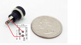
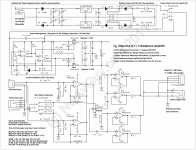
I'm building a desktop version of the O2 with a kit I got from HeadnHifi. Everything has been good so far but I'm not sure on how to connect the power jack as it is a two prong panel mount one while the original one has three prongs. I looked at the schematics but I'm not quite sure how to interpret this:
 The jack I have looks very much like this one here: 1.7mm DC Power Panel Mount Jack - VETCO.NET with one prong being longer and the other shorter. Can you help me on the wiring? Thanks!
...but I'm not sure on how to connect the power jack...
Like this, below.
You use the middle two power jack holes on the O2 PC board. The side O2 power jack hole is for an unused switch in that original jack. The power input plug that goes into the jack is AC (check to make sure you are using an AC transformer secondary and not DC!) so there is no polarity. You could run it like I've drawn, or you could swap the two wires on the back of your external jack (longer and shorter jack prongs don't matter).
Attachments
Last edited:
Thanks! I completely forgot that the O2 uses AC and not DC. I guess the power switch can also be used for DC and that's why it has one longer terminal. By the way, what type of wire would be suitable for connecting the jack to the PCB? I'm using CAT5 twisted pair for the signal path from to the RCA but I think that'll be too thing for the power line.
I'm using CAT5 twisted pair for the signal path from to the RCA but I think that'll be too thin for the power line.
The CAT5 would be just fine for the power wiring. The O2 pulls at most around 300mA(rms) = 0.3A(rms). CAT5 is supposed to be 26AWG worst case (smallest). From the table here
American Wire Gauge table and AWG Electrical Current Load Limits with skin depth frequencies and wire strength (scroll way down)
you have a maximum ampacity of 2.2A for 26AWG. 40 ohms for 1000ft, or 0.04R for 1 foot. At 300mA that would be around a 10mVac drop, insignificant since it is feeding voltage regulators. Any inductance the wiring introduces would be a good thing, since it would only affect RF frequencies (way above AC line 50/60Hz) and help keep them from getting into the O2 innards.
Last edited:
Just finished assembling my O2 board and followed the instructions for checking resistances and all measured OK.
I removed U2 and was going to measure the supply voltages across via the battery terminals as per the instructions. Plugged in the transformer (15vac) and there was a noise and puff of smoke from somewhere on the board.
I finally found the problem (I think); The two pins on the U6 regulator (nearest the filter caps - numbers 1 and 2 on the reg = input and ground?) had a solder bridge hence a dead short.
Looking at the schematic, I checked the D4 diode for damage and found it was kaput (it was short circuited) so my next step is to replace that.
Would anything else have been damaged? As the solder bridge was between the input and ground on the regulator I'm hoping that the reg won't be damaged but not sure about the other components - filter caps; C3,C5?
Any advice appreciated.
I removed U2 and was going to measure the supply voltages across via the battery terminals as per the instructions. Plugged in the transformer (15vac) and there was a noise and puff of smoke from somewhere on the board.
I finally found the problem (I think); The two pins on the U6 regulator (nearest the filter caps - numbers 1 and 2 on the reg = input and ground?) had a solder bridge hence a dead short.
Looking at the schematic, I checked the D4 diode for damage and found it was kaput (it was short circuited) so my next step is to replace that.
Would anything else have been damaged? As the solder bridge was between the input and ground on the regulator I'm hoping that the reg won't be damaged
but not sure about the other components - filter caps; C3,C5?Any advice appreciated.
Attachments
- Home
- Amplifiers
- Headphone Systems
- The Objective2 (O2) Headphone Amp DIY Project