I measured my batteries, they were about 8.8V each. Anyway weird thing, yeasterday my O2 worked for few minutes fine, but then as I turned power on and off, it stopped working again.. I'll take some measurements and post here later..
I experienced the same thing. It was intermittent for a while and then just silent.
Sent from my mobile thinger using the tapawhatsit
Has anyone tried out the LME49990 on the O2?
The LME49990 is a fantastic part. OPC used it in the "Wire" headphone amp. The THD + noise vs. frequency graph is just amazing. But unfortunately it wouldn't work/fit in the O2. The 49990 is only available in surface mount and only in single op-amp packages, vs. the dual op-amp through-hole NJM2068 in the O2.
The LME49990 is a fantastic part. OPC used it in the "Wire" headphone amp. The THD + noise vs. frequency graph is just amazing. But unfortunately it wouldn't work/fit in the O2. The 49990 is only available in surface mount and only in single op-amp packages, vs. the dual op-amp through-hole NJM2068 in the O2.
What if something like this were used?
Dual SOIC LME49990 DIP8 Adapter | eBay
What if something like this were used?
Lol! You've got me there.
 That is a good find. I'm always surprised at what is out there.
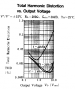
 The other problem though is the AC specs of the NJM4556A output chips are rather hideous compared to the LME49990 and would likely cover up any improvements. Check out the THD vs. output voltage graph in the NJM4556A data sheet:
http://semicon.njr.co.jp/eng/PDF/NJM4556A_E.pdf
That is for a gain of 30dB, so luckily things get better at unity gain as RocketScientist's measurements showed.
But... I'm always one for trying things! From the specs the 49990 should work, and at that relatively low price it would be fun just to try.
Check out the THD vs. output voltage graph in the NJM4556A data sheet:
http://semicon.njr.co.jp/eng/PDF/NJM4556A_E.pdf
That is for a gain of 30dB, so luckily things get better at unity gain as RocketScientist's measurements showed.
THD graphs are well known for not giving much insight into how things actually sound. Nobody that I know of can hear 0.01% THD. Music is made up of a lot of low-level signals rather than a few high level ones so what matters is more what's going on on the left-hand side of that graph. I have a hypothesis that what we need there is the distortion has to disappear below the noise as the level goes down. The LF distortion probably does but that 20kHz distortion curve which remains stubbornly above the LF ones is problematic for SQ. With a normal opamp what's limiting that HF distortion is the input (LTP) stage, so biassing it into class A at the output has little effect. We really need an opamp with a different architecture.
I just had a look at the LME49990 DS but they're too coy, they don't show what JRC show here - how THD vs level varies with frequency. But the THD plots do show a rise at 20kHz.
Attachments
Last edited:
"....I think The Wire is a solid design and I like the LME49600 a lot. I also like the fact he ran Audio Precision measurements to prove the performance--that's very rare in DIY. On the downside I think The Wire is more expensive than it needs to be. It also uses surface mount parts which are a challenge for some people.
I started a DIY audio thread regarding a more simple design ( http://www.diyaudio.com/forums/headphones/186188-national-lme49600-reference-design-project.html ). We got a bit off track in the thread, but I'm still researching similar designs. My goal was a reasonably priced, no BS design, that's easy to build and performs well....."
Quoted by RS in user comments
NwAvGuy: Cmoy eBay Headphone Amp
As for opamp rolling in O2 read,
"....In other words, without updating the rest of design (perhaps including even the PC board), the op amp may be at least somewhat unstable or otherwise unhappy. And because most instability is at ultrasonic or RF frequencies, the person doing the swap may not even know they just took a giant step backwards. Even RMAA can’t “see” ultrasonic and RF problems..."
http://nwavguy.blogspot.in/2011/08/op-amps-myths-facts.html
IMHO LME49990 or 49600 will require very careful PCB layout (not the O2 PCB layout)
Last edited:
Quick question I haven't built my O2 yet (I have the material), but from my first experience with the cMoyBB, I noticed that a few of the joints are black by accident. Is that a very bad thing; should I desolder it? Or is the reason it is black is because I've heated it too long by accident? It might be one of the joints that I reheated and reapplied solder with desoldering it first, I am not very sure.
Also, to clarify, too less solder on IC -- or basically any parts with extremely small leads -- is fine as long as it covers the lead up? Generally, although it is both bad, less solder > more solder?
One last soldering question: Does it damage the lead or pcb a lot when I reheat it for the purpose of desoldering it, then reheating it for the purpose of soldering it?
Black solder joints? Definitely no good.
I can't say for sure why it's black. A contaminant or overheating? Or both? Those joints should be desoldered and redone. Apply flux and don't use more heat than is necessary for a good shiny fillet.
I wouldn't say a joint has to have a perfect fillet with ~45° slope. There shouldn't be any voids in the hole alongside the lead - that's a sure sign of insufficient solder. Too much solder is bad also. My advice is don't settle for too little or too much; get it right and it will eventually become second nature.
No damage is done by soldering/desoldering if it is done right. If you "can't get it," pause and let all the parts cool down. Don't fight it with the soldering iron stuck to the board.
Problems with test
I've just completed everything and done resistor and voltage tests. Most of things are ok, but some values are different than expected.
In resistor tests R1&R2 should be 100-200, I've measured them 238. R5 should be 100K, I have it 109K. R25 should be 330K, but it's 316K.
As for voltages, when testing with AC, only difference from NwAvGuy test diagram is U4 pins 4 and 8. They should be 11.8V (+/-), but are 11.6V (+/-).
When I disconnect from AC, and try those pins with batteries only, they have 8.9V. It should be also 11.8V?
Are resistor measurements in acceptable values? Did I do something wrong?
It's DIY bought on Head'n'HiFi, and as I see, everything is as written in O2 BOM.
Looks like what you may be dealing with is nothing but component tolerance. R1 & R2 are current-limiting resistors only; their values aren't critical unless they are too low and allow excessive charge to the batteries. It looks like your other resistors are part of the engineering change for the power management circuit. I didn't implement that change and so will refrain from comments, except to say it has to do with the O2 turning on and off, not its actual operation. The voltages you show are fine. AC power provides a few more operating volts than battery power.
If these are the worst things you've found in the tests, get some cheap headphones for first power-up testing and listening. If that passes, plug in your favorite headphones and enjoy your new O2!
If these are the worst things you've found in the tests, get some cheap headphones for first power-up testing and listening. If that passes, plug in your favorite headphones and enjoy your new O2!
I have two O2+ODAC combo in same enclosure and i have small problem with noise. At full volume, i can hear a noise with very sensitive IEMs.
With bare O2 without ODAC what i build before there is dead silent even at full volume. Well, it is insane level, i do not even tried to play music at this volume but i want just make sure that everything is ok.
I just found that:
With bare O2 without ODAC what i build before there is dead silent even at full volume. Well, it is insane level, i do not even tried to play music at this volume but i want just make sure that everything is ok.
I just found that:
from http://www.diyaudio.com/forums/audio-poutine/214751-audiopoutine-odac-mounting-kit-instructions.htmlhere was some unconfirmed reports of hiss and hum from the odac installed on top of the o2..
I have two O2+ODAC combo in same enclosure and i have small problem with noise.
I've been wondering if putting something digital (noisy) that close to the audio input parts is such a good idea.
With the O2 powered up, try disconnecting the USB cable to the ODAC and then listen for noise again in your headphones with the volume and gain all the way up again. With the USB cable pulled out that cuts the power to the ODAC and should quiet all the digital stuff. Does the hiss go away like that?
Disconnecting USB cable almost removes noise, but amp is not still dead silent like O2 without ODAC in enclosure. It maybe because ground traces in input jack are cutted so input "floats" and pull noise from air. I noticed that ground wire makes big difference in combo, bare O2 is dead silent even without it.
BamboszeK - interesting! You are right, without the inputs grounded the O2 will pick up some noise. In this case the O2 inputs would still go back to ground via the input circuit of the ODAC, but with the power removed there is no telling how much resistance to ground would be present in the ES9023 chip. A lot of additional resistance would increase the Johnson noise on the O2 input and that alone would bump up the background noise slightly.
Have you twisted each input wire together with a ground wire going from the ODAC to the O2? If not that would definitely be worth doing.
Have you twisted each input wire together with a ground wire going from the ODAC to the O2? If not that would definitely be worth doing.
At beginning, i want to thanks you for help. Yeah, input wires are twisted together, i've used standard cat 5e ethernet wires.
Summing, looks like mounting ODAC inside O2 decreases performance slightly, but mostly inaudible or imperceptibly in real use.
Ah, and one more small question. JDS Labs and NwAvGuy suggests slightly different wiring methods. I've used JDSLabs method 1, connecting to P1 with one ground wire.
http://www.jdslabs.com/pdf/Instructions_ODAC_DIY.pdf and http://nwavguy.blogspot.com/2012/05/odac-may-update.html
Last edited:
Ah, and one more small question. JDS Labs and NwAvGuy suggests slightly different wiring methods. I've used JDSLabs method 1, connecting to P1 with one ground wire.
Yeah, it sounds like the ODAC increases background noise a little, but probably not enough to really be a problem.
On the wiring, I would recommend NwAvGuy's way of doing it using two wires. The twisted pair thing works because equal currents in opposing directions in the two wires produce equal electromagnetic fields around the two wires, but in opposing directions so they will cancel. Using the two wire approach ups the chances for getting equal but opposing field cancellation around the wires.
Looks like what you may be dealing with is nothing but component tolerance. R1 & R2 are current-limiting resistors only; their values aren't critical unless they are too low and allow excessive charge to the batteries. It looks like your other resistors are part of the engineering change for the power management circuit. I didn't implement that change and so will refrain from comments, except to say it has to do with the O2 turning on and off, not its actual operation. The voltages you show are fine. AC power provides a few more operating volts than battery power.
If these are the worst things you've found in the tests, get some cheap headphones for first power-up testing and listening. If that passes, plug in your favorite headphones and enjoy your new O2!
Thank you!
I did test and everything seemed ok, so I took my AKG K702 having doubts, can they sound better with O2. They sure can! I'm so glad I decided to try this DIY, after 15 years from last time I soldered something.
All in all, it went much easier than expected. At the end I realized that U5 and U6 are soldered too high, and had to re-solder them... They were extremely hot when doing that and I was scared I burnt them. But it seems they're not easy to kill.
And then realized that outer battery is too high (by a hair) to fit into case. Doesn't bother me as I plan to use it as desktop amp for now.Great to hear you're enjoying your tunes.
You could probably adjust the battery connector a little to get it to fit. It has a lot of metal mass, so what I do sometimes in those situations is remove as much solder as I can, then melt the remaining solder and use long-nose pliers to wiggle the part while the solder rehardens, which leaves the part loose.
You could probably adjust the battery connector a little to get it to fit. It has a lot of metal mass, so what I do sometimes in those situations is remove as much solder as I can, then melt the remaining solder and use long-nose pliers to wiggle the part while the solder rehardens, which leaves the part loose.
- Home
- Amplifiers
- Headphone Systems
- The Objective2 (O2) Headphone Amp DIY Project