OK, I've completed the O2 with the new caps.
Now I've started to measure and things don't quite add up.
U2 is installed, and all the measurements are fine except for P2.
I've included a picture to make things clearer;
On both points at P2 I get ~1.4V instead of the 0-0.008V I should be getting.
Any input on troubleshooting would be greatly appreciated.
Thank you very much.
Now I've started to measure and things don't quite add up.
U2 is installed, and all the measurements are fine except for P2.
I've included a picture to make things clearer;
An externally hosted image should be here but it was not working when we last tested it.
On both points at P2 I get ~1.4V instead of the 0-0.008V I should be getting.
Any input on troubleshooting would be greatly appreciated.
Thank you very much.
Last edited:
Hello! I already got the Objetive O2 PBC from JDS labs. Now im buying all the components.
Are the Op Amps NJM4556AD and NJM4556A the same thing? Because my suplier only has the latter (NJM4556A) so im not shure if they are the right ones.
I also got problems getting the High Eficiency LED , how should i ask for it at the store?
Is it 0.5mA or just a simply 10mA led? That part got me confused on NwAvGuy post.
U2 is installed, and all the measurements are fine except for P2.
On both points at P2 I get ~1.4V instead of the 0-0.008V I should be getting.
Any input on troubleshooting would be greatly appreciated.
With just U2 installed, the outputs at P2 are floating, they aren't connected to anything. There is nothing to measure there until the op-amps are installed.
Are the Op Amps NJM4556AD and NJM4556A the same thing? Because my suplier only has the latter (NJM4556A) so im not shure if they are the right ones.
I also got problems getting the High Eficiency LED , how should i ask for it at the store?
Is it 0.5mA or just a simply 10mA led? That part got me confused on NwAvGuy post.
Did you check any datasheets to see what the difference is between the 4556A and the 4556AD? The "D" refers to the package, in this case DIP8. The other available packages are DMP8 (NJM4556AM), SIP8 (NJM4556AL) and SSOP8 (NJM4556AV). All of them are NJM4556A, as long as you get one in DIP8 package you have the right one.
As for the LED, read NWAVGuy's blog again, the LED has to operate on about 0.5mA, and it has to have the right forward voltage drop. Look up the part on Mouser's site, get the data sheet or specs, and show it to your supplier.
So , if i cant get the NJM4556AD op amp , can i just use in U1-U3-U4 (Nwavguy PBC) the NJM2068D ? Would i loose some performance?
Thanks
You would lose a lot of performance. The 2068 cannot provide nearly as much current as the correct op-amps.
With just U2 installed, the outputs at P2 are floating, they aren't connected to anything. There is nothing to measure there until the op-amps are installed.
Thank you very much nezbleu, so you think I can just go on in the measurement process with the OP-amps installed?
I wasn't sure and did not want to destroy the OP-amps...
All right, thanks to you guys, the amp is up and running!
I'm glad there was no soldering mistake, everything worked right from the start
So here it is;
The next step will be building a case, I'll keep you posted.
I'm glad there was no soldering mistake, everything worked right from the start
So here it is;
An externally hosted image should be here but it was not working when we last tested it.
The next step will be building a case, I'll keep you posted.
Did you check any datasheets to see what the difference is between the 4556A and the 4556AD? The "D" refers to the package, in this case DIP8. The other available packages are DMP8 (NJM4556AM), SIP8 (NJM4556AL) and SSOP8 (NJM4556AV). All of them are NJM4556A, as long as you get one in DIP8 package you have the right one.
As for the LED, read NWAVGuy's blog again, the LED has to operate on about 0.5mA, and it has to have the right forward voltage drop. Look up the part on Mouser's site, get the data sheet or specs, and show it to your supplier.
Thanks a lot , yes indeed it is the DIP8 so it must be the same , im getting it as soon as possible. Regarding the LED , i'll try another place , i think i will find it out.
Cheers
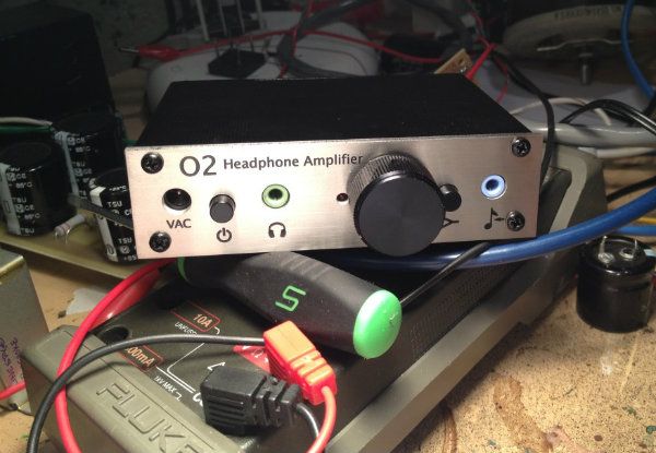
The LED forward drop is 1.79Vdc. See the photo of the DMM attached to this post:
http://www.diyaudio.com/forums/head...rc-diode-cap-heatsink-mods-3.html#post3194263
http://www.diyaudio.com/forums/head...rc-diode-cap-heatsink-mods-3.html#post3194263
The LED forward drop is 1.79Vdc. See the photo of the DMM attached to this post:
http://www.diyaudio.com/forums/head...rc-diode-cap-heatsink-mods-3.html#post3194263
Thanks for that link , but im still confused anyway.
When i went to the suply shop and i asked for a Red Led that worked with at least 0.5mA , they treated me like a crazy person and told me " we only sell 20mA and 10mA , maybe as low as 5mA Leds "....and forget about SMD or PBC Mount type....at least here
(Cordoba , Argentina )
Then i went to RocketScientist's O2 post and cheked the bill of materials.
The Led part number is "638-MV5764.MP4B2" , so i cheked that on Mouser Electronic web page. That Red LED datasheet says its 10mA and VF 2.0 .
here is the PDF link:
http://www.everlight.com/lamp_datasheet/ds300477.pdf
Next time i go to the suplier i will just ask for it with that part number.
If they still don't get it or don't have it , can i just use a standard (no pcb mount) 10mA Red Led ? I mean , it should have the adequate foward current drop , i don't know why RocketScientist's says its a "High Efficiency" Led if the datasheet says its 10mA , thats pretty standard for low consumption .
Cheers , Stefano
Thanks for that link , but im still confused anyway.
Here is a long-winded answer that should help to clear some of the terminology up.
LED forward voltages drop with decreasing current. The datasheet is saying that at 10mA through the LED its Vf will be around 2.0. That is the "test current", something the manufacturer has picked to be a common usage condition. But with the the O2 LED current dropped down to 0.5mA we are getting Vf = 1.8V. Turns out you can drop a LED's current down so low the light isn't even visible to the eye anymore (way below that datasheet test current number), but the LED is still doing its thing and maintaining a (slightly lower) forward voltage. People use LEDs in circuits all the time as voltage references, like in the O2, but with the LED current so low no (visible) light is coming out.
So for the O2 the LED current is set by the 40.2k series resistor R6. The good news is that you can make that resistor anything you need it to be to get the 1.8V from the red LED. Changing R6 won't mess up anything else in the circuit but may draw a bit more current from the batteries if you make it smaller. For example, with the O2 on AC power, the power rails are at 11.8Vdc each (12V minus two diodes), for a total of (2 x 11.8Vdc) = 23.6Vdc across R6 and the LED. Subtract out the 1.8V for the LED and your LED current through the resistor is (24V - 1.8V) / 40200 ohms = 0.54mA.
Most standard LEDs would not produce much, if any, visible light at that low of a current. Your supplier is right, 5mA would be more typical rating, with 1mA about the smallest rating you will find on datasheets - but remember, you can run them at lower currents even if no light comes out. The "high efficiency" label just means the LED will actually produce enough light to be visible even at this smaller (than the 10mA data sheet test current) low 0.54mA number. When the O2 is running on batteries that are almost dead, the LED and resistor have only about 14Vdc across them. So the LED current then is even smaller - only (14 - 1.8) / 40200 = 0.3mA.
Red LEDs have a forward voltage between 1.6Vdc and 2.0Vdc (see the Vf table here https://en.wikipedia.org/wiki/Light-emitting_diode). If you are willing to give up actually seeing the LED light up you can use a "non high efficiency" one and just run it at a lower current. If your local supplier has one that is labelled on the package as "2.0Vdc", you will probably find that if you run it at a small current that Vf can be dropped to 1.8V. Works great, even though you can't see much, if any, light coming out anymore. Just make R6 slightly bigger or smaller as required. Different Red LEDs will have slightly different Vfs in the range, too. Try other models if needed to find one that runs around 1.8V.
If you have some resistors and a DMM handy, put the led and a 39k resistor in series with two 9V batteries (like my avatar, lol!), to get 18Vdc (roughly midway between the O2 high and low power rail numbers), and measure the voltage drop across the led. Then just change that resistor up or down to get the Vf = 1.8Vdc, then solder that resistor into the O2 in place of R6.
The other way around is if your supplier has a red LED that has Vf=1.8Vdc, but it needs a bigger current than 0.5mA to get there, just make R6 smaller as needed. For example, say you've measured that your supplier's LED will hit Vf=1.8Vdc at a current of 5mA. Using the highest case 23.6V rails for the O2, your R6 would then need to be (23.6V - 1.8V) / 0.005A = 4360 ohms = 4.3K standard value. You will loose a small amount of O2 run time on batteries increasing the LED draw to 5mA from 0.5mA, but at least the O2 will work.
Good luck!
Last edited:
tecnogadget - here is a 3rd option for you.
You can also just use a red LED and (R6) resistor combination with a forward voltage of 2.0Vdc. The only effect would be the O2 turning off slightly later, when the batteries drop to around 6.94V each rather than 7.07V, if using R25 = 1.5M and R9 = 33k. But you want to use the lowest LED current you can that will produce a stable Vf since the batteries will run down faster with the increased LED current.
If your supplier has a "high efficiency" or "super bright" LED with a rating of Vf=2.0 at 10mA or 20mA, it will be more likely to still produce some visible light when the current is dropped down to 0.5mA or 1mA. That is why RocketScientist used that type of LED in the design, so he could run the LED with as small a current as possible that would still produce light, to minmize battery loading.
Awesome! Thanks you very much AGDR for taking the time and effort with your response.
That makes it more clear and explains it all.
And..ups! I forgot to mention before , that i was planning to run the O2 from AC Power , not Batteries. So i think im on the lucky rails , since dropping battery life won't affect me in this case , isn't it?
I'll do that because when i started using the Headroom Total Air Head with AC , it turned out to have somewhat better response at higher volume levels , it kind of reproduced detail more effortless , with more space and dynamics.
Awesome! I forgot to mention before , that i was planning to run the O2 from AC Power , not Batteries.
That does make things a lot simpler! You could simply run the LED at Vf = 2.0Vdc with 5mA or 10mA current (R6 = 4.3k and 2.1k). No concerns about the increased current shortening battery life or altering the power managment turn-off point for the batteries by a few tenths of a volt.
qusp has a really good point. With the LED in backwards it would be "off", causing the comparator input to go up to the positive rail, exceeding the chip's common mode input range. Unpredictable output stuff would ensue. Another good reason to set up a test circuit first - like my avatar - to make sure which lead on the LED is + and which is - .
Has anybody from India assembled the O2
Dear all,
Has anybody from India assembled the O2 ? If yes pls PM me from where they have sourced components from. All I have are 2 bare PCBs & bunch of NJR2068 & passives. Don't have JRC4556AD (the most essential component).
Regards,
availlyrics
Dear all,
Has anybody from India assembled the O2 ? If yes pls PM me from where they have sourced components from. All I have are 2 bare PCBs & bunch of NJR2068 & passives. Don't have JRC4556AD (the most essential component).
Regards,
availlyrics
- Home
- Amplifiers
- Headphone Systems
- The Objective2 (O2) Headphone Amp DIY Project