Ethan,
I don't wish to start a debate on caps, this has been beaten to death in other threads at diyA and other forums...suffice to say I'm somewhat partial to the caps I mentioned and specifically to Polystyrene on this application and this is only my 2 cts. We do have capable instrumentation for the work we do as DIY audio including a tektronix scope but no harmonic distortion analyzer and in no way we will measure or compare caps...life is too short to spend it that way... Lets enjoy the music.
No offence implied,
Cheers, Tony
First off I want to thank AGDR and the rest of the crew here that help us with ideas and comments to trace an overcome the issues with my first DIY. A special thanks to APASGEAR (dad) for time and patience, TBH I was discouraged with the troubles that evolved during the build but you easily traced the spots and oriented me with the procedures to overcome them.
Going back to subject the O2 is running as I type, but not is was not an easy task, after a recheck was definitive that R16 path to pin 6 in U1 was gone (if existent), what appeared to be and easy fix it turn out difficult since during todays test ans surgery I found out that I screwed up R16 path to pin7, aint that a beauty!
What we did was a bridge between pin6 and 7 with the 1.5k resistor and the 220pF cap in parallel under the board directly soldered to the IC socket, just like the original layout but out of the board, it worked a treat! Problem solved.
Then I changed the original C20 for a styrene one to match the one used in the bridge described above. BTW we left the original C19 cap in its original location to avoid further damage to the PCB, obviously is not working any more since the paths are gone and overridden.
Just for the record I did have a short between gain switch and via hole...solved and at some point I mixed the resistors from the gain sockets and during the final test I had and imbalance between channels witch jumped from one side to another depending the gain switch position...men! at that moment I was about to bang my head to the wall LOL.
I just tested the O2 paired with my Meelectronics CC51 IEM´s wich are 16 omhs, sweet sounding match and this phones definetly favor the O2 amplication. Then it was time to bring the big guns and pull out the Ety´s ER-4p....so far so good, the amp as intended does not add any coloring to the sound, maybe a whisker of warmth witch goes very well with the this IEM´s analytic sound signature.
Adding a bass boost as I plan to do so will make me happy camper since this phones IMHO are a tad lacking on the bottom end to reach a "rich/full" reproduction of the recordings....OH! BOY! I just noticed that this involves messing around with R16 again! Auch!
Dad! get the soldering iron ready
Last edited:
Just curious - which caps are you replacing, C19 and C20 or also C11 and C12? What part numbers have you picked for the replacements? Thanks.
The AD712 does look like an interesting part! The gain/phase plot still has a break at 100kHz like the NJM2068 (good audio chips). The phase plot is more linear. And a thousand times less input bias current and input offset current being FET vs. bipolar (vs. the NJM chip)! The noise specs are better, too. The quiescent current is no higher and the THD is 10x better, although the O2 output stage would likely cover up any improvement there.
Hmmm.... I'm going to have to order some of those in and give the chip a try.
Digi-Key - AD712JNZ-ND (Manufacturer - AD712JNZ)
Go for it! I´ll try the AD712 in the weekend...who knows maybe my non golden ears will hear some difference LOL but its worth a try and more since we have one lying around asking to be mounted and driven
Guys...need some help here...
The Dual Audio Potentiometer 20 x 6mm or 15 x 6mm shaft (RK09712200MC):
Waths the posision of this on the board...i mean...the board has much more holes than the Potentiometer....
And i already saw pics of this component in different positions...
Someone can explain ?
Thanks
The Dual Audio Potentiometer 20 x 6mm or 15 x 6mm shaft (RK09712200MC):
Waths the posision of this on the board...i mean...the board has much more holes than the Potentiometer....
And i already saw pics of this component in different positions...
Someone can explain ?
Thanks
Guys...need some help here...
The Dual Audio Potentiometer 20 x 6mm or 15 x 6mm shaft (RK09712200MC):
Waths the posision of this on the board...i mean...the board has much more holes than the Potentiometer....
A 15mm shaft pot, like that RK09712200MC, goes in the front set of holes closest to the board edge, so you wind up with unused holes behind it.
A 20mm shaft pot goes in the holes farthest from the board edge, so you wind up with unused holes between the board edge and the front of the pot. IMPORTANT: there is a post on RocketScientist's blog where someone discovered the front metal face (with the mounting threads) of their 20mm pot was touching some of those unused holes in front of it and causing a short. With a 20mm shaft pot it would be a good idea to put something thin, like a TO-220 mica washer, temporarily between the pot body and the PC board when soldering to make sure there is a little space there.
Last edited:
What we did was a bridge between pin6 and 7 with the 1.5k resistor and the 220pF cap in parallel under the board directly soldered to the IC socket, just like the original layout but out of the board, it worked a treat! Problem solved.
Hey good solution!
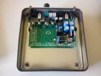
There is a lot of space there between the bottom of the board and the B2-080 case bottom.Many thanks...before i read your comment i saw the 20mm and the 15mm writed on the board...thanks anyway...almost complete...only waiting for jacks because in mouser are out of stock....
and for the B2 case from the jokener groupbuy....:S
and for the B2 case from the jokener groupbuy....:S
A 15mm shaft pot, like that RK09712200MC, goes in the front set of holes closest to the board edge, so you wind up with unused holes behind it.
A 20mm shaft pot goes in the holes farthest from the board edge, so you wind up with unused holes between the board edge and the front of the pot. IMPORTANT: there is a post on RocketScientist's blog where someone discovered the front metal face (with the mounting threads) of their 20mm pot was touching some of those unused holes in front of it and causing a short. With a 20mm shaft pot it would be a good idea to put something thin, like a TO-220 mica washer, temporarily between the pot body and the PC board when soldering to make sure there is a little space there.
IMPORTANT: there is a post on RocketScientist's blog where someone discovered the front metal face (with the mounting threads) of their 20mm pot was touching some of those unused holes in front of it and causing a short. With a 20mm shaft pot it would be a good idea to put something thin, like a TO-220 mica washer, temporarily between the pot body and the PC board when soldering to make sure there is a little space there.
What I do in those cases is I grab my wifes nail polish when she is not looking and seal those holes that could cause a short with a tiny droplet. Did the same with the via next to the gain switch
and some other boards.cosmetics have some use after all...
Stefan
What I do in those cases is I grab my wifes nail polish when she is not looking and seal those holes that could cause a short with a tiny droplet. Did the same with the via next to the gain switch
cosmetics have some use after all...
Stefan
Ha! good solution! What I did was a piece of mylar paper between them
Re: AD712 for the gain stage, this might actually work fairly well. At least its high voltage noise won't be a particular concern (I once helped a guy mod his Rotel RA-980BX amp which uses one as a gain amp after the volume pot and understandably is a fairly hissy affair in stock form).
Do note that the AD712 must be used at higher than unity gain since it exhibits phase reversal if either input gets too close to the negative rail.
Do note that the AD712 must be used at higher than unity gain since it exhibits phase reversal if either input gets too close to the negative rail.
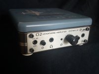
Fossilized O2 amp
All assembled and sounding great!
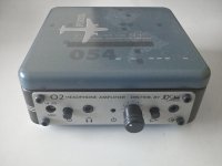
I used a box from a wallet I bought some time ago and modded it as an O2 enclosure. Finished, light, perfect sized for further additions like RCA´s, Bass Boost switch, ODAC, etc, and free
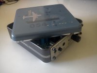
Just did a cut on the front end of the box, drilled some holes for the torx screws to hold the JDS aluminum panel, some mounting holes for the PCB and added some white rubber feet to compliment the bundle.
Pretty happy with the final result...sexy!
All assembled and sounding great!
I used a box from a wallet I bought some time ago and modded it as an O2 enclosure. Finished, light, perfect sized for further additions like RCA´s, Bass Boost switch, ODAC, etc, and free
Just did a cut on the front end of the box, drilled some holes for the torx screws to hold the JDS aluminum panel, some mounting holes for the PCB and added some white rubber feet to compliment the bundle.
Pretty happy with the final result...sexy!
Attachments
@BlueRob - Great job - nice retro look, very stylish. However, the knob looks too modern, might be better with a pointer knob, something like this : http://www.ebay.co.uk/itm/Pointer-Potentiometer-Knob-Black-Hard-Plastic-2-Pack-/290614949071
Last edited:
All assembled and sounding great!
I used a box from a wallet I bought some time ago and modded it as an O2 enclosure. Finished, light, perfect sized for further additions like RCA´s, Bass Boost switch, ODAC, etc, and free
Just did a cut on the front end of the box, drilled some holes for the torx screws to hold the JDS aluminum panel, some mounting holes for the PCB and added some white rubber feet to compliment the bundle.
Pretty happy with the final result...sexy!
that looks good.. going to steal this idea
-joe
All assembled and sounding great!
I used a box from a wallet I bought some time ago and modded it as an O2 enclosure. Finished, light, perfect sized for further additions like RCA´s, Bass Boost switch, ODAC, etc, and free
Just did a cut on the front end of the box, drilled some holes for the torx screws to hold the JDS aluminum panel, some mounting holes for the PCB and added some white rubber feet to compliment the bundle.
Pretty happy with the final result...sexy!
Hey BlueRob.
Please send me 12 of these, I pay for the freight and a few pints!
Brgds
@BlueRob - Great job - nice retro look, very stylish. However, the knob looks too modern, might be better with a pointer knob, something like this : Pointer Potentiometer Knob Black Hard Plastic (2 Pack) | eBay
Think I have one of those some where, I´ll look for it to see if it fits, THB I like this round one but I´m trying to find something similar but a bit bigger and flatter. I took this one from my Mini3 (cof cof)
that looks good.. going to steal this idea
-joe
Stealing an idea is called plagiarism and I must say the design is copyrighted...not!
Go for it and don't forget to post some pics of your amp Hey BlueRob.
Please send me 12 of these, I pay for the freight and a few pints!
Brgds
Soldering as fast as I can... I´ll let you know when your order is ready LOL.
Glad you liked it mate
I connected one of my DAC's to the O2.
http://www.diyaudio.com/forums/digi...hread-show-n-tell-too-14.html#post2962050#133
The internal connection really needs some buffering since it sounded very thin.
Brgds
http://www.diyaudio.com/forums/digi...hread-show-n-tell-too-14.html#post2962050#133
The internal connection really needs some buffering since it sounded very thin.
Brgds
Newbie seeks advice:
I'm just getting to the battery terminals and need to discharge a cheapo 9v battery so that I can get the fit right. What resistor would be appropriate for a nice rapid but not dangerous discharge?
Also I saw mention of not using alkaline batteries for testing. I think that's all I have. Would I get away with sony carbon Zinc or Daewoo Super heavy Duty 6F22(p)?
One more issue: R25 measures .5M ohms when soldered in. I mistakenly thought that it must be faulty so I replaced it with another which I tested prior to the correct 2.7M ohms (older kit so prior to RS's adjustment to 1.5M ohms). However it then also measured as .5M when in situ. All the other resistors measure at their rating when soldered in. Is this normal?
I realise the above are naive questions: I decided on the O2 as my intro to electronics and will soon be buying some books but right now I have near zero knowledge or understanding.
@lorriman
Easiest thing to do is to use a 9v or 12v bulb of any size to discharge the battery. Don't forget to allow for the thickness of any double-sided tape you are going to use to fix the batteries in place with, especially if it is the foam sort.
I think the advice about not using alkaline batteries for testing only applies if you are going to be building and using the charging circuit - obviously you should only use rechargable NiMH batteries in this case.
For more on resistance measurements, see the 'Measure Resistances' paragraph in the 'Initial DIY Testing' section of 'O2 Details' http://nwavguy.blogspot.co.uk/2011/08/o2-details.html
Last edited:
Newbie seeks advice:
I'm just getting to the battery terminals and need to discharge a cheapo 9v battery so that I can get the fit right. What resistor would be appropriate for a nice rapid but not dangerous discharge?
Also I saw mention of not using alkaline batteries for testing. I think that's all I have. Would I get away with sony carbon Zinc or Daewoo Super heavy Duty 6F22(p)?
One more issue: R25 measures .5M ohms when soldered in. I mistakenly thought that it must be faulty so I replaced it with another which I tested prior to the correct 2.7M ohms (older kit so prior to RS's adjustment to 1.5M ohms). However it then also measured as .5M when in situ. All the other resistors measure at their rating when soldered in. Is this normal?
I realise the above are naive questions: I decided on the O2 as my intro to electronics and will soon be buying some books but right now I have near zero knowledge or understanding.
Any 9v battery will do to help you place and solder the battery terminals IMO what is important is that you dont use the alkaline and the wall adapter at the same time since the amp will try to charge this non-rechargeable batts and will cause damage.
Can´t help you much with R25 since my schematic has the new resistor values....What is important is that R25 read in your DMM the 2.7m ohms that you mention before installing it. Measuring afterwards could be tricky since other components come into play, it can be done but you have to take into account the other things around.
BTW as a rule of thumb...always check resistors with you DMM before installing them, they can be bad, be off beyond tolerance or simply is not the correct value. Better be safe than sorry. A carpenter will say measure twice cut once...this applies to other fields
Last edited:
- Home
- Amplifiers
- Headphone Systems
- The Objective2 (O2) Headphone Amp DIY Project