Since you wish to do this, lets look at it.
Mullard circuit looks like a good choice.
Since its a beginner project, a single set of output tubes is a requirement.
There are choices for outputs:
Classic choice is class AB1 UL with EL34 / 6L6GC / 6550 /KT88
This requires Global Feedback.
Global feedback requires that each different output transformer used has its own compensation network.
Class A2/AB2 Triode requires either interstage transformers or followers, but may not require Global feedback. Same general Tube choices.
Source followers might be ok, CF or IT are right out for an inexpencive first project.
I will be interested in what you come up with.
Good luck.
Doug
Class A2/AB2 Triode requires either interstage transformers or followers, but may not require Global feedback. Same general Tube choices.
Source followers might be ok, CF or IT are right out for an inexpencive first project.
In an earlier post source followers or rather mosfets are off limits.
A solid state rectifier and operating point tweaks for different tubes is fine, but no added CCS's or FET drivers, etc.
Basically an updated ST-70 without any added bells and whistles, as TubeLab suggested, would work well. Ie. the DynaMull with the B+ lowered a bit. I'm currently puzzling out how to accomplish that.
The easiest way is to use a power transformer with a bit less voltage, like a 720 VCT or a 750 VCT. The other common way is to reduce the value of the power supply input cap, but this takes simulation or trial and error.
Is there a pspice modeler that supports tubes without me having to create my own components from scratch? We (well, they...) use NI Multisim at work, but its support for tubes is pretty anemic. I'd have to build my own symbols and plug in some models I get from elsewhere.
I use LTspice, a free download from Linear Technology. Vacuum tube models are not going to be found included in the library in any spice simulator. However they are relatively abundant on the internet. The accuracy of these models varies from good, to well not so good. The accuracy also degrades when you operate a tube further from the "expected norm". Using a 12AT7 and 6L6GC model from the internet the simulated version of a Simple SE amp agrees with the real thing.
There are many good reasons to want more than flea power, and to not want horns, but that's a different discussion and not one I am really interested in. I have a pretty good handle on amplifier power. But in general, I think 25-50 watts is plenty enough for typical home use, even with 'normal' 87-89dB speakers......I hold an irrational regard for the adrenalin boost that comes with running "big iron". It's like commuting to work in funny car -- fun to step on the gas every now and again, but mostly just expensive, useless and fun to look at and talk about. That's not something I would tackle with tubes though. It wouldn't make sense at any level.
First off I don't know of any funny car that would be street legal. I do have an old Dodge Challenger that makes over 500 HP, and incinerating the rear tires is a fun experience, but I haven't driven it to work in years, too many cell phone yacking bozos on the road today, and it wakes up every cop in 3 zip codes!
I also fully understand that my NS-10's have reached x-max by about 25 watts, yet I continue to build bigger amps. My recent experiences with P-P amplifiers in the 100 to 200 WPC range reveals that there is something to be gained by running an amplifier that you will NEVER clip. If you have been to my web site you know that I believe that "too much power is not enough". I have 800 watts worth of OPT's and I mean to use it all, I just haven't got there yet. I have however been building tube amps for over 40 years, and yes I have blown up a lot of parts. I will blow up more in the process of learning, that is just the way it is.
I have enough experience to know my goals are perfectly reasonable. If nobody else wants to participate, that's fine, I'll get it done anyway. I always do. I rarely listen to nay-sayers. I joined a martial arts club at age 40 against everyone's advice and didn't regret that for any of the 5 years it took to get a black belt. I joined a hockey team at age 50 playing with 20-somethings, much to the shock and horror of my wife and both our parents. No regrets. If the kids slam gramps into the boards for no reason, they end up in the bleachers with their $400 titanium stick wrapped around their $400 helmet.
I understand where you are coming from. I work in advanced development enginnering for a major electronics company. At the peak of the boom there were about 5000 people in the facility where I work. At least half of those are engineers. The average age is probably about 30. The economic downturn and other factors have shrunk the population to far less than half of that. There are less than 20 people my age left. I am still there because I go and do what people say can't be done.
11 years ago they put in a gym, and said that it was free to employees. About 10 years ago 7 of us started going. I was 47 the other 6 were from 24 to 35. I was by far the oldest and the smallest (155 pounds) of the group. Now only 1 of those people still work there and he doesn't go to the gym any more. Perseverance, an engineering problem solving approach, and serious attrition, has now made me one of the biggest lifters in the gym (200 pounds 6% body fat). Yeah, they said that the old man couldn't do it, now thay ask how.
I have no doubt that you (or anyone else with reasonable intelligence, patience, the ability to listen and learn) can do what you set your mind to. I also think that you might be looking for a while before you find exactly what you are looking for, since none of our suggestions seem close enough. Again, I will offer a few suggestions.
The Dynamull schematic that you have seems to be the one that got your attention. You could build it as it stands, in such a way that it can be tweaked on. You can then experiment on it to see what works, and what doesnt. I often just hook parts together without a schematic, and then tinker until I have something that works, some smoke, or I give up. Then I do it again. You have an idea what you want, so you have a starting point.
If I were doing this, I would make some changes to the Dynamull circuit. Something more like the Plitron design. If this is something you are interested in, I can make educated guesses as to the changes and the component values, and you could experiment. If that doesn't appeal to you, maybe there is another option that I'm not seeing.
If you want a tested Mullard circuit that can be made with modern components, I will get there. If you havent figured it out first, you can follow along.
I also think that you might be looking for a while before you find exactly what you are looking for, since none of our suggestions seem close enough.
There are scads of schematics out there that look good to me (heck, they're almost identical) but they all seem to have little flaws as determined by the folks here. It's easy for me to keep showing schematics and asking opinions. I learn quite a bit from the comments about those schematics.
The Dynamull schematic that you have seems to be the one that got your attention.
I'm not too hung up on that one. Its flaw is with the voltage structure. I'll keep looking. No hurry.
Something more like the Plitron design. If this is something you are interested in, I can make educated guesses as to the changes and the component values, and you could experiment.
A too generous offer, but I'd rather build something with a track record for this project, even if its track record is 50 years old.
If you want a tested Mullard circuit that can be made with modern components, I will get there. If you haven't figured it out first, you can follow along.
I will be watching. I'm happy to offer my assistance if you need help with graphics or whatever (you don't need any help with writing). Just let me know if/when you need something. Please don't let my goals affect your project though.
..Todd
Any flaws in this one (attached)? It looks fine to me.
Or the Claus Byrith (Lundahl) Mullard revision?
..Todd
Or the Claus Byrith (Lundahl) Mullard revision?
..Todd
Attachments
Any flaws in this one (attached)? It looks fine to me.
Or the Claus Byrith (Lundahl) Mullard revision?
..Todd
Bad news Taj. The Claus Byrith schematic is the same one we've been trying to fix for months now. Thats where the schematic originally came from.
") You've just gone full circle. Now you see the problem i've had finding a working schematic.
You've just gone full circle. Now you see the problem i've had finding a working schematic.
Last edited:
The Claus Byrith schematic is the same one we've been trying to fix for months now.
Hi TubeMack,
For the KT88 project? Were you trying to fix it, or trying to modify it use KT88's. (I'm content with EL34's for this build.) It's not the same as the first schematic you posted inthe KT88 thread. I think you might be referring to a different thread that I haven't seen. I'll search to see what the issue was. Doesn't matter much anyway, more fish in the sea.
It's the Leak one attached to that last message that I thought looked most interesting. But then I can't spot flaws easily.
What are the advantages/disadvantages of taking its bias from a tap off the cathode tail? It's a local feedback loop too, since the AC is not bypassed, right? Well, I can see the obvious advantage of not requiring a bias power supply feed. There must be a disadvantage or all amps would do it this way.
..Todd
Last edited:
my $.02
Taj: I don't think you'll have any problems building a P2P PP amp as a first go. You might let the smoke out of a few things along the way but that's part of the process.
I had zero experience building any sort of amp two years ago and have since built Gingertube's baby huey PP EL84 and Poindexter's 6GK5/EL34 music machine. I smoked a power transformer early on which is supposed to be hard to do....but given a large enough mains fuse and some beginner wiring techniques, not so hard
Buy some iron, dust off the soldering iron, and build a breadboard of something. If you don't like the outcome, you can always recycle the iron into something else. It's the difference between riding a bicycle and reading about how to ride a bike...
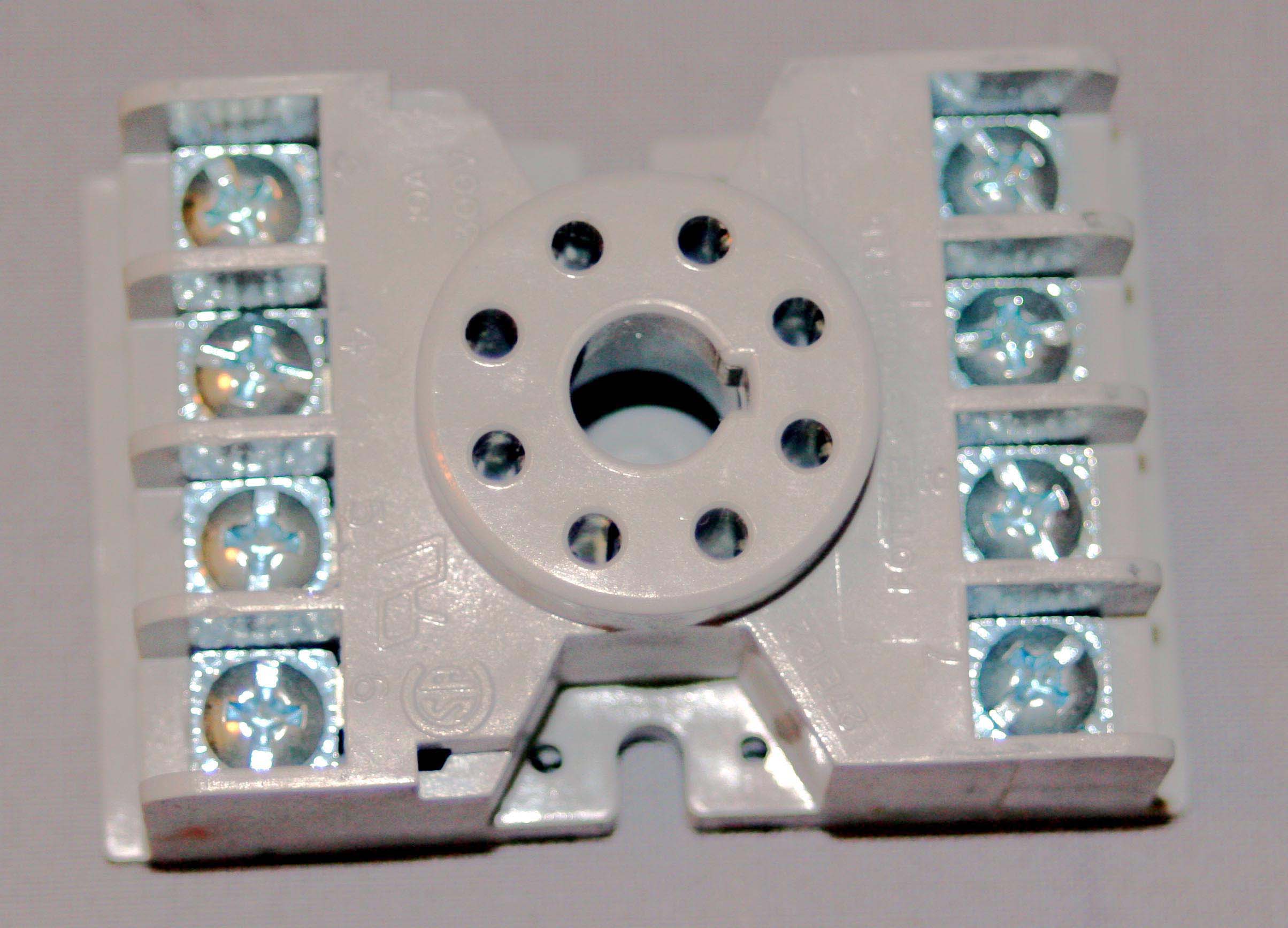
You can pick up octal breadboarding sockets from Apex Jr here:
Tube Scokets
Potter Brum Field 27E122
Once you get something you like, build a chassis. Sounds like you are going to end up with an EL34 or KT88 PP amp, so source a pair of output transformers and a power transformer (or 2 for monoblocks) that would be suitable for either. If your transformers are sized power-wise for KT88 use, they'll also work for EL34. The only tough decision is the primary impedance of the output transformer, 5K may be a good compromise for the above tubes in triode & UL.
Input your desired output tubes in TDSL and look at the chart for various operating conditions for EL34 & KT88 in triode, UL, etc. It comes down to B+, Va, bias current, output transformer primary impedance, and triode/UL topology. This is a quick way to see what primary impedance is required for triode/UL. Using a larger primary impedance results in a little less power out and less distortion, and a lower impedance results in greater power and distortion out.
TDSL Tube search
If you want simple, there are several 2 stage schematics around that use the phase splitter as the first stage. Both amps above are two stage, and Triode Dick's Mono Bill is also a 2 stage KT88 design although I have not found many/any opinions on that design. Less stages=less stability issues related to phase shift.
Taj: I don't think you'll have any problems building a P2P PP amp as a first go. You might let the smoke out of a few things along the way but that's part of the process.
I had zero experience building any sort of amp two years ago and have since built Gingertube's baby huey PP EL84 and Poindexter's 6GK5/EL34 music machine. I smoked a power transformer early on which is supposed to be hard to do....but given a large enough mains fuse and some beginner wiring techniques, not so hard
Buy some iron, dust off the soldering iron, and build a breadboard of something. If you don't like the outcome, you can always recycle the iron into something else. It's the difference between riding a bicycle and reading about how to ride a bike...
You can pick up octal breadboarding sockets from Apex Jr here:
Tube Scokets
Potter Brum Field 27E122
Once you get something you like, build a chassis. Sounds like you are going to end up with an EL34 or KT88 PP amp, so source a pair of output transformers and a power transformer (or 2 for monoblocks) that would be suitable for either. If your transformers are sized power-wise for KT88 use, they'll also work for EL34. The only tough decision is the primary impedance of the output transformer, 5K may be a good compromise for the above tubes in triode & UL.
Input your desired output tubes in TDSL and look at the chart for various operating conditions for EL34 & KT88 in triode, UL, etc. It comes down to B+, Va, bias current, output transformer primary impedance, and triode/UL topology. This is a quick way to see what primary impedance is required for triode/UL. Using a larger primary impedance results in a little less power out and less distortion, and a lower impedance results in greater power and distortion out.
TDSL Tube search
If you want simple, there are several 2 stage schematics around that use the phase splitter as the first stage. Both amps above are two stage, and Triode Dick's Mono Bill is also a 2 stage KT88 design although I have not found many/any opinions on that design. Less stages=less stability issues related to phase shift.
Same project. The schematic had already been modified for KT88's by that point. Other issues were the 12ax7 was not liked, nor the biasing scheme.
I see. Again, no big deal.
..Todd
Taj: I don't think you'll have any problems building a P2P PP amp as a first go. You might let the smoke out of a few things along the way but that's part of the process.
Exactly.
When I was a kid, I built a Heathkit tube radio kit in my dad's TV shop, while he build the Heathkit colour TV.
My, how times have changed...Todd
Last edited:
What are the advantages/disadvantages of taking its bias from a tap off the cathode tail? It's a local feedback loop too, since the AC is not bypassed, right? Well, I can see the obvious advantage of not requiring a bias power supply feed. There must be a disadvantage or all amps would do it this way.
..Todd
The only substantial difference between the Leak and Mullard schematics in your post above is here. The 5-20 is directly coupled from the first stage to the inverter, and the Leak is cap coupled. In the Leak, the inverter is biased by the voltage drop across the top resistor setting the g-k voltage, where in the 5-20 the inverter current is set by the voltage drop across the tail resistor. I think the 5-20 is more elegant and has 1 fewer cap in the signal path FWIW.
There is no feedback loop because the LTP inverter is essentially a differential amplifier,, having nominally constant current (no signal) across the tail resistor. The signal current is between the 2 sections of the tube.
I think it's worthwhile to gain a deep understanding of these 2 points to help fully understand the circuit's operation.
Cheers,
Michael
PS I kind of like the circuit values in the 5-20 one also but it's hardly a black and white kind of thing
Thanks Michael. I appreciate the info.The only substantial difference between the Leak and Mullard schematics in your post above is here. The 5-20 is directly coupled from the first stage to the inverter, and the Leak is cap coupled. In the Leak, the inverter is biased by the voltage drop across the top resistor setting the g-k voltage, where in the 5-20 the inverter current is set by the voltage drop across the tail resistor. I think the 5-20 is more elegant and has 1 fewer cap in the signal path FWIW.
Thanks again. Either I have a mental block regarding diff amps, or I haven't found a good explanation yet. I only semi-understand.There is no feedback loop because the LTP inverter is essentially a differential amplifier,, having nominally constant current (no signal) across the tail resistor. The signal current is between the 2 sections of the tube.
I think it's worthwhile to gain a deep understanding of these 2 points to help fully understand the circuit's operation.
I'll keep pounding myself on that topic until it clear(er)...Todd
Last edited:
Thanks Michael. I appreciate the info.
Thanks again. Either I have a mental block regarding diff amps, or I haven't found a good explanation yet. I only semi-understand.
..Todd
It just occurred to me that you might think of the LTP as having current "feedback" from one cathode to the other. One might call it differential feedback. There is an offset current in the tail until both sides of the LTP are in balance.
For a thought exercise, consider that a CCS is a little better than a resistor in the tail because it gets out of the way of this current feedback, where a resistor shunts some of the signal current.
Cheers,
Michael
It just occurred to me that you might think of the LTP as ...
Another piece of the puzzle. It all helps.
Thanks Michael...Todd
Any flaws in this one (attached)? It looks fine to me.
Or the Claus Byrith (Lundahl) Mullard revision?
..Todd
Just a shameless BUMP...
Any opinions on these two circuits? (in message #64) Using them as-is, but updated power supplies -- no significant mods otherwise.
..Todd
Hi,
I was directed here by a mate.
Working on a "DynaMull" at this moment. Results are promising:
DynaMull
Cheers!
Congratulations!
I believe lots of people will be happy to get such a board.
- Status
- This old topic is closed. If you want to reopen this topic, contact a moderator using the "Report Post" button.
- Home
- Amplifiers
- Tubes / Valves
- The no-brainer project, some questions