Stop bothering J-P with those e-mails.") I posted the schematic here:
I posted the schematic here:
http://www.diyaudio.com/forums/showthread.php?s=&postid=173347#post173347
I posted the schematic here: http://www.diyaudio.com/forums/showthread.php?s=&postid=173347#post173347
Peter,
Thanks for the schematics. However, what you do not consider is that some people actually read the articles and do not simply follow some schematics. You can learn quite a bit with the text. I usually do not restrict DIY to a simple copying act, wether it is for a gainclone or a dac.
Toiemoi
Thanks for the schematics. However, what you do not consider is that some people actually read the articles and do not simply follow some schematics. You can learn quite a bit with the text. I usually do not restrict DIY to a simple copying act, wether it is for a gainclone or a dac.
Toiemoi
I usually do not restrict DIY to a simple copying act, whether it is for a gainclone or a dac.
Sounds good but we all have to start somewhere don't we ?
Sure
Yes, there is definitely a starting point... for a gainclone it may be LM application notes or Thoersten schematics.
Making something exactly like X or Y does not help you understand what are the keypoints of the design unless you read the articles, designer notes.... Without having prior knowledge of the designer comments, it is going to make the improvement stage much harder and painfull, not to mention it may also be harder and more frustrating to fit the design to your needs. I'd rather spend the extra-time reading an article and start experimenting a little more informed and with a thoughtful approach.
Toiemoi
Sounds good but we all have to start somewhere don't we ?
Yes, there is definitely a starting point... for a gainclone it may be LM application notes or Thoersten schematics.
Making something exactly like X or Y does not help you understand what are the keypoints of the design unless you read the articles, designer notes.... Without having prior knowledge of the designer comments, it is going to make the improvement stage much harder and painfull, not to mention it may also be harder and more frustrating to fit the design to your needs. I'd rather spend the extra-time reading an article and start experimenting a little more informed and with a thoughtful approach.
Toiemoi
Re: Sure
I'm not sure if I understood you correctly, but you seem to imply that what I'm doing is a simple coping act of a schematic posted by someone else? If you look at my implementation, it is true (as you say somwhere else) that my approach was inspired by Thorsten IGC schematic and only because it sounded so good I decided to pursue it even further. It's totally stripped of any parts that are not completely needed and it is as simple as inverted amp can get: 2 resistors and one chip. I don't even think that application notes can give you that much of a hint. So it's hard to say that one is copying someone, unless you insist that I change 220k feedback resistor to 200K.
As to a DAC it is also totally stripped version of what Kusunoki suggests, without any filters and unnecessary components. I added quite a few extra parts that I thought might be helpful and used different PS. So what exactly is your point?
And what is that you are trying to say here? Are you blaming me for not posting the articles as well?
I don't have much time to try to understand key points of design. I find much more pleasure in implementing someone elses schematics (but modified to my likening), than pursuing circuit design. I guess, it's a matter of prefferences, and doing what one can do the best. My profile says 'full time diy", yours: "proffessional student'. That might be a good explanation of our differences (if such are)
toiemoi said:Peter,
Thanks for the schematics. However, what you do not consider is that some people actually read the articles and do not simply follow some schematics. You can learn quite a bit with the text. I usually do not restrict DIY to a simple copying act, wether it is for a gainclone or a dac.
Toiemoi
I'm not sure if I understood you correctly, but you seem to imply that what I'm doing is a simple coping act of a schematic posted by someone else? If you look at my implementation, it is true (as you say somwhere else) that my approach was inspired by Thorsten IGC schematic and only because it sounded so good I decided to pursue it even further. It's totally stripped of any parts that are not completely needed and it is as simple as inverted amp can get: 2 resistors and one chip. I don't even think that application notes can give you that much of a hint. So it's hard to say that one is copying someone, unless you insist that I change 220k feedback resistor to 200K.
As to a DAC it is also totally stripped version of what Kusunoki suggests, without any filters and unnecessary components. I added quite a few extra parts that I thought might be helpful and used different PS. So what exactly is your point?
toiemoi said:
Making something exactly like X or Y does not help you understand what are the keypoints of the design unless you read the articles, designer notes.... Without having prior knowledge of the designer comments, it is going to make the improvement stage much harder and painfull, not to mention it may also be harder and more frustrating to fit the design to your needs. I'd rather spend the extra-time reading an article and start experimenting a little more informed and with a thoughtful approach.
Toiemoi
And what is that you are trying to say here? Are you blaming me for not posting the articles as well?
I don't have much time to try to understand key points of design. I find much more pleasure in implementing someone elses schematics (but modified to my likening), than pursuing circuit design. I guess, it's a matter of prefferences, and doing what one can do the best. My profile says 'full time diy", yours: "proffessional student'. That might be a good explanation of our differences (if such are)
NONOZII DAC Output Stage
Hello,
I think I will try to build a NONOZII DAC, but I will try a tube output stage. I have found a Thunderstone Audio Schematic for TDA1543.
Does somebody can help me to find the best connection between pins 6,7,8 of TDA1543 and thunderstone output stage ?
My question could be seem stupid, but I'm not a specialist of DAC and I prefer to ask
Thank you
Pascal.
Attachments
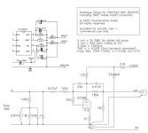
You need two of these tube circuits, one on pin 6 and one on pin 8. The 1.5 k resistors and the rest of the Nonoz II schematic at pin 6 and 8 is replaced by Thorstens design. Make a 1k pot between pin 7 and earth with a 500 ohm in series and adjust the pot for 4.3 V on pin 6&8 in rest.
Good luck!
Fedde
Good luck!
Fedde
dear all,
You seem to like CS8412 a lot (I use it too). From all the published circuits I see, I have 2 suggestions:
- Decouple filt pin with 10 nF to ground ? Crystal IC designers put it next to MCK pin, they "slightly" lack of understanding of RF crosstalk.....(in average 1 pF is present between 2 pins)
- Redesign the loop filter in order to decrease incomming jitter ?
enjoy,
Guido Tent said:
You seem to like CS8412 a lot (I use it too). From all the published circuits I see, I have 2 suggestions:
- Decouple filt pin with 10 nF to ground ? Crystal IC designers put it next to MCK pin, they "slightly" lack of understanding of RF crosstalk.....(in average 1 pF is present between 2 pins)
- Redesign the loop filter in order to decrease incoming jitter ?
This is also known as the Monkeysect filter but with different values. Since I saved the quote of Monkeysect I hereby quote it:
Try a 470 or 500 ohm resistor in series with 0.22 microfarads; and up the loop to 3rd order by adding a 3300 picofarad cap from the loop filt pin directly to ground. This pin is *extremely* sensitive to noise pickup, keep lead lengths short. This attempts to keep adequate loop phase margin, maintaining settling time and avoiding peaking.
Unfortunately there is no single best number here, and elsewhere for that matter.Notice the vague square law correspondence. Here, the resistor is about half of the data book, and the cap is about 4x. Coincidence? Synchronicity? Just math...
Within [or "below"] loop bandwidth the source phase noise dominates, and above it the local vco phase noise dominates.
Hence the pll "tracks" the incoming frequency and artifacts with a settling time approx inverse to the loop bandwidth, so any peaking is to be avoided.If one has the time to twizzle, a better solution [but not the one true way (tm)] is to place the master clock right at the DACs [fed by it's own regulated power supply] registering/reclocking the DACs and "slaving" the transport to that master clock, guaranteeing synchronicity [of the clocking type, not the cosmic type] and eliminating dependence on the pll/vco.
So 470 Ohm with 0.22 uF from pin 20 to ground and one 3.3 nF from pin 20 directly to ground. It is of most importance that wire leads are very short ( read: use a PCB for the DAC and use SMD for the filter ) otherwise the results will be worse than with the original filter.
Dupply for CS8412 PLL
Hi, Use low noise analog supply for the loopfilter section of the CS8412:
http://db.audioasylum.com/cgi/m.pl?forum=digital&n=36950&highlight=supply+cs8412&r=&session=
Orginal post by Wildmonkeysects in this thread:
http://db.audioasylum.com/cgi/m.pl?forum=tweaks&n=30297&highlight=loopfilter+cs8412&r=&session=
Guido Tent said:dear all,
You seem to like CS8412 a lot (I use it too). From all the published circuits I see, I have 2 suggestions:
- Decouple filt pin with 10 nF to ground ? Crystal IC designers put it next to MCK pin, they "slightly" lack of understanding of RF crosstalk.....(in average 1 pF is present between 2 pins)
- Redesign the loop filter in order to decrease incomming jitter ?
enjoy,
Hi, Use low noise analog supply for the loopfilter section of the CS8412:
http://db.audioasylum.com/cgi/m.pl?forum=digital&n=36950&highlight=supply+cs8412&r=&session=
Orginal post by Wildmonkeysects in this thread:
http://db.audioasylum.com/cgi/m.pl?forum=tweaks&n=30297&highlight=loopfilter+cs8412&r=&session=
Re: Good Low Noise PSU
Hi Pascal,
I am sure Thorsten (K.Y.W.) has some fine schematics with choke filtered supplies for tubes. I am sorry as I am not into tubes. Can not give you advice here.
Did you check his website and forum?:
http://thunderstoneaudio.nav.to/
http://groups.yahoo.com/group/Thunderstone_technical/
PTSOUNDLAB said:Hello,
does somebody have a schematic or a link for a good very low noise simple PSU (250V without choke if possible) for the Thunderstone analogue stage for TDA1543 I have put in my "NONOZII DAC Output Stage" post ?
Thank you boys.
Pascal.
Hi Pascal,
I am sure Thorsten (K.Y.W.) has some fine schematics with choke filtered supplies for tubes. I am sorry as I am not into tubes. Can not give you advice here.
Did you check his website and forum?:
http://thunderstoneaudio.nav.to/
http://groups.yahoo.com/group/Thunderstone_technical/
CD Rom and Nonoz
Accordingly to information which I found on the web, digital output from CD Rom is in TTL format. I want to use Cd rom as a transport. The circuit which converts TTL signal to SPDIF contains 1:1 transformer and 74HC04 chip ( is taken from this website: http://www.epanorama.net/documents/audio/spdif.html ).
DAC which I want to build is a Fedde's NonozII. I thought to put conversion circuit inside of CD Rom enclosure. I would also like to use this DAC with other transports, not only with my CD rom. What would be the best in this situation? Should I put another transformer inside of the DAC?
Re: Good Low Noise PSU
Pascal
I suggest to at least look athis tool
http://www.duncanamps.com/psud2/index.html
and you may consider posting in a tube related section of this community
I prefer passive supplies, or shunt regulators
PTSOUNDLAB said:Hello,
does somebody have a schematic or a link for a good very low noise simple PSU (250V without choke if possible) for the Thunderstone analogue stage for TDA1543 I have put in my "NONOZII DAC Output Stage" post ?
Thank you boys.
Pascal.
Pascal
I suggest to at least look athis tool
http://www.duncanamps.com/psud2/index.html
and you may consider posting in a tube related section of this community
I prefer passive supplies, or shunt regulators
- Status
- This old topic is closed. If you want to reopen this topic, contact a moderator using the "Report Post" button.
- Home
- Source & Line
- Digital Source
- The new Nonoz II DAC page !!!