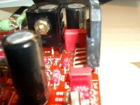
There's a minor issue with the Twisted Pear version 1.2 boards and the LM3886TF - the edge of the board extends out by about 0.5mm from the mating surface of the LM3886TF. When you fit a heatsink to the LM3886TF, it might not make contact with the entire surface of the chipamp, but only near the mounting bolt. At least, that's what I saw today on one of my builds with a Version 1.2 PCB and the LM3886TF.
Possible workarounds:
1) Use an LM3886T and an insulating shim.
2) Use an LM3886TF and any shim, maybe an aluminium bear-can piece.
3) Gently file away about 0.5mm off the edge of the PCB with a hand file.
4) Reduce the AC supply to 24-0-24 or lower, to reduce the possibility of SPIKE being triggered.
I suggested that.3) Gently file away about 0.5mm off the edge of the PCB with a hand file..
You can go back and read the abuse the Members threw at me.
Yea, I found that edge problem when I took these units apart last week. The grease had imprinted in only the top third of the chip footprint on the heat sink. For the testing I'm doing now I can angle the top of the sink back toward the board to get a full match. For final assembly I will be able to machine a groove in the heatsink to allow for 90 degree alignment. There is also the possibility of using risers so the HS just clears the board.
Andrew - I remember those interchanges. Reminded me of when someone threw a shoe at George Bush") .DUCK!
.DUCK!
So unless I hear otherwise, I'm assuming there are no board components that need adjustment or replacement in term of excessive heat or voltage. I'll order some 24s next week.
Andrew - I remember those interchanges. Reminded me of when someone threw a shoe at George Bush
.DUCK!So unless I hear otherwise, I'm assuming there are no board components that need adjustment or replacement in term of excessive heat or voltage. I'll order some 24s next week.
Last edited:
I can't simply understand...
I've built 10 of this modules and 4 Gainclone modules, all with LM3886TF and not a single one needed to adjust the PCB with a hand file...
If mounted and soldered carefully (in my tutorial one simple method can be found) the LM3886 is perfectly in line with PCB margin.
After soldering the LM3886 position is still 'adjustable' a bit by gently manipulating it.
then you have different PCBs from those that exhibit the problem.I can't simply understand...
I've built 10 of this modules
If mounted and soldered carefully the LM3886 is perfectly in line with PCB margin.
Dario, I did follow your instructions (drill first - solder later) to the letter, even with linuxguru's V1.3 boards. It appeared to be a fool proof method.All appeared good till I took the heatsink off and then tried to reassemble. I agree it doesn't make sense but the error was there as evidenced by the grease footprint. I considered just bending everything back into position buy using the edge of the board as the fulcrum but didn't know how much stress the LM3886 could handle. As Siva said, the overhang is very, very small - but it is there on the boards I have. I was a machinist at one time in my life and I did the proper tests to verify the error.
In retrospect, I believe just mounting the chip higher off the board (maybe with a spacer) would eliminate the problem thereby increasing the flexibility of the pins.
In retrospect, I believe just mounting the chip higher off the board (maybe with a spacer) would eliminate the problem thereby increasing the flexibility of the pins.
Last edited:
I've the same PCB as all GB buyers.
From the tutorial (underlining added):
Apply (don't solder it, just put in place leaving 1-2mm from bending of pins and PCB) first LM3886 to the PCB. Use it to
sign the hole posistion on heatsink, drill it and then mount the LM3886 to it.
From the tutorial (underlining added):
Apply (don't solder it, just put in place leaving 1-2mm from bending of pins and PCB) first LM3886 to the PCB. Use it to
sign the hole posistion on heatsink, drill it and then mount the LM3886 to it.
Attachments
Last edited:
Absolution.
Dario,
You are hereby absolved of all guilt and blame from the "Michigan Contingent".
I think we are agreeing but I'm just adding that for us noobees, a spacer at that step can/could be helpful. Please don't take any offense. Your commitment to and time spent with this fantastic piece of electronics is greatly appreciated and valued by all who pass this way.
Highest Regards,
Bob M.
Last edited:
Dario,
You are hereby absolved of all guilt and blame from the "Michigan Contingent".
I think we are agreeing but I'm just adding that for us noobees, a spacer at that step can/could be helpful. Please don't take any offense. Your commitment to and time spent with this fantastic piece of electronics is greatly appreciated by all who pass this way.
Hi Bob,
no offense and no problem at all.
It's just that this design was criticized too much...
For sure Russ White made a good PCB with some minor problems such:
- LM3886 mounting requires some care
- Some positions (C7, C9,C21, C1 and C2) are too small to accomodate best components.
But when a PCB is designed you can't anticipate all possible problems that could arise, particularly when people is going to use components not indicated in the original BOM.
LinuxGuru made a nice job overcoming some of this problems with his mods to the design.
Bob, glad you found your problem and it's not too serious. Others have said that once the protection has tripped, the chip may be compromised. I don't know. What would be the point of providing protection if it didn't really protect the integrity of the chip?
Just checked my red PCB's from the "ultimate" GB against the green boards from the previous "economy" group buy, and there is a difference of .023" in distance from center of 3886 mounting holes to the edge of the board. The holes on the red board are too far away; the green boards mount perfectly with an insulating pad. This should have been caught during the initial inspection of samples, but I can see how it could have been overlooked. I don't know what the manufacturing tolerance is for dimensions to the edge of a board, but I'd be surprised if it's less than .015". Perhaps it must be specified if needed to be smaller. Hole to hole dimensions are likely .005", a reasonable amount.
Bob, I used to be a machinist, too! I used my Brown & Sharpe scale and a magnifying glass to measure.
I have not yet mounted my populated red boards to a heatsink, but, upon close inspection, I can now see there will be a gap between chip face and heatsink that will NOT be closed by the insulating pad. If using the insulated chip, there is no easy remedy. Solve the problem any way you can. A perfectly flat, adequately thick metal spacer will suffice if both sides are covered with thermal paste. Carefully filing or sanding the edge of the board, as Andrew suggested and I originally criticized, may prove difficult for some, but would be the best fix if done properly. Relieving the heatsink with a groove or step, or mounting the board below the edge of the heatsink, as Bob suggests, will work. Bending all those leads of the 3886 chip by that amount is probably not a good idea. If using an insulating pad, bending a smaller amount might be acceptable. Soldering the chip at an angle (1/2 degree?) and mounting the heatsink out of plumb might also work, but then your entire assembly is crooked. I guess that's what Dario's solution provides and a lot of other builders have probably done, intentionally or by accident.
Peace,
Tom E
Soldering the chip at an angle (1/2 degree?) and mounting the heatsink out of plumb might also work, but then your entire assembly is crooked. I guess that's what Dario's solution provides and a lot of other builders have probably done, intentionally or by accident.
Hi Tom,
no, not at all!
It could be that the tutorial is not so clear but my mounting method doesn't conteplate mounting the chip at an angle...
If you look the photo previously attached the LM3886 is in plumb.
For sure Russ White made a good PCB with some minor problems such:
- LM3886 mounting requires some care
- Some positions (C7, C9,C21, C1 and C2) are too small to accomodate best components.
But when a PCB is designed you can't anticipate all possible problems that could arise, particularly when people is going to use components not indicated in the original BOM.
LinuxGuru made a nice job overcoming some of this problems with his mods to the design.
Thanks, and I fully agree that the issues with the Twisted Pear boards are very minor, and have mostly arisen because of changes to the original BoM to accommodate 'better' (usually physically larger) components.
If done carefully, I see no problem with filing the edge of the PCB. You just have to be careful not to hit the edge of the signal ground plane, mute trace or a few nearby pads. There's plenty of clearance, and back in the old days before CNC machine tools, filing/fitting was routinely employed for every kind of assembly. The Bastard Rasp is your friend.
Last edited:
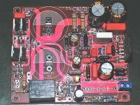
OK, here's a sneak peek at the Rev C Version 1.4 PCB - this is the first board that is being (partially) populated. If all goes well on the assembly and initial audition, this will be the stock board for all the kits I offer. All recent BoMs should fit on this board as well. The board shown has stock Sn/Pb (HASL) finish, but RoHS-compliant immersion-gold (ENIG) finish will also be available.
Some (incremental) improvements/features are:
- 12mm pitch resistors at various locations (R5-R12, etc.) allows the use of 0.5W (Holco, Allen-Bradley, etc.) resistors comfortably.
- 5/7.5/10/15mm pitch at C4 allows larger Wima MKP10s or other brand MKPs.
- Added C22, C23 in parallel with C4 and C7. These can be (optionally) populated with high-quality specialty caps like polystyrenes, FKP2s, silver micas, etc.
- 8mm outline at C6, C11 includes sufficient space to comfortably fit 10mm caps. (In a pinch, 12 mm caps can be mounted a few mm above the PCB surface).
- 12mm outline at C1, C2 includes sufficient space to comfortably fit 16mm caps (e.g. Muse KZ as shown, Black Gate STD, etc.)
- 12mm outline at C9 allows a 16mm cap (BG STD) to be squeezed in, if C21 is omitted or mounted on the solder side.
- 12mm pitch for ZD1, ZD2 allows the use of On Semi 1N5349B 5W, 12V zener (shown in pic) or similar.
- Low-inductance multifilar traces between the chipamp and C4/C22; and between the LM318 and C7/C23 , helps raise the 1/sqrt(LC) resonant frequency for those segments.
- More clearance for R1, R4 for convection cooling.
- R3 has dual pitches for both 9mm pitch Fukushima Futaba and TO-220 Caddock power resistors.
- More pitch options for C13, from 10mm to 22.5mm
- Better shielding for the small-signal areas around the LM318.
- Improved pad-to-pad clearances at various locations, most notably near R15, R16, R19, R20.
- More clearance for the mute trace from the edge of the PCB.
- Reduced circulating-current area between power traces to the chipamp.
- Hatched polarity marking on the silkscreen for most of the outlines of electrolytic caps reduces the possibility of screw-ups during assembly.
Attachments
Last edited:
Man thats a pretty sweet lookin board Siva.
Bob, I had the same problem but resoldering fixed it. Dario's way would have saved me. Its just that if the chip leans a little while you solder the first row then you go soldering the next and it is now impossible to move the chip at all to be flat on the heatsink. If you just desolder the front row of pins then apply to heatsink and solder the row again all should be well. Its not a bad idea to insulate behind the board with a piece of tape in case the board should somehow touch the sink. Some board houses are cutting with saws and some are cutting with chopping knives. The knives are not very accurate. Also some houses score it then break them apart which is even worse. I think, however, that these were a saw cut and looked pretty good to me.
Uriah
Had some trouble with the TI318P's
Hi All,
I'd like to report a little problem I recently encountered that seems to have been caused by the substituted TI318P. I had used a LM 318 in my original build, but had tried substituting the TI318P during tweaking. At first there was no problem, it sounded fine, maybe a wee bit warmer that the LM318. Later I changed the power resistors to carbon film and changed the coupling cap to a audio cap theta with very nice results. I though that I was done. But after operating the amp for ~ 1 hour I noticed that one channel kept dropping out, then would come back every few minutes, like the spike protection was being triggered. Next I noticed a hiss had appeared in both channels, then both channels began to drop out after only ~ 1/2 hour of operation. When I checked the amp chips were hot even though they are firmly attached to large heat sink. Before the TI318P swap I couldn't even get them to get barely warm after many hours. The bottom line is that when I put the LM318's back in all was well again, dead quite, no hiss, no dropout, no hot LM3886. All told the TI chips had maybe 6 hours on them. So I'm guessing that the TI chips failed, or were about to fail in this service and were causing occillation.
PJN
I haven't run into this issue specifically with the TI chips, but it does sound like some kind of instability. Are they confirmed to be authentic TI chips? The ones I'm using have LM318P written in black text on a silver surface, with the TI logo in black as well. Also check that R1, R4 are adequately rated - 2W should be fine, 1W may be cutting it fine.
Look Ma - No Fans !
In the computer world they have a phrase “RTFM” dealing with documentation. Here it might be “Read the Meter”. In my rebuild of the Twisted Pear V1.2 MyRefs (red board) I found I had put a 47K and not a 47R in position R42. I don’t know enough about the circuits to be sure that was the problem but the sound and the temperatures are completely functional now. Been at max volume for over an hour and all is well with the world. I do remember reading someone’s advice to verify resistors before mounting – we learn by our mistakes. I hope others can learn from mine and as they say “trust but verify”.
Thanks for all the help,
Bob M.
- Home
- Amplifiers
- Chip Amps
- The new "My Ref" Rev C thread