udailey said:I am not entirely sure what you mean but I would put each RCA signal through an input cap if you measure any DC from your CDP. A poorly constructed preamp can give some DC if its active and a poorly constructed passive pre can make noise but I dont think its going to generate any DC. If you have no ouput caps on your CDP then your amp should have them. A CDP can give a few volts of it without a cap in the way of DC on each channel. This would destroy your speakers quickly. So measure then make your choice. Dont try to figure it all out first. Measure then decide.
Please email me the parts you would like again and I will order from Mouser for you today.
Uriah
Please ignore my last posting regarding DC offset....I might be tangle up with some AC/DC confusion here.....Anyway thanks for the advice...!!!
")
Check your email....
While trying to diagnose my broken amp, I took voltage readings at lots of points and compared them to the working amp. Interesting that the working amp has 16.5 volts at C14, not 24 as noted on the schematic. Has anyone else ever measured the voltage there? There is 24 volts at the junction of D2 and D3, but 16.5 volts after R14.
On the broken amp, I am getting 30 volts all over the place: BOTH ends of D2 and D3, both ends of R3 (should be zero, I believe), at C14, etc. Voltages on the transistors are all weird, too. The only normal readings are at ZD1, ZD2, R1, R4, C3, C6, C8 and C11, so I know the power supply is okay. I checked all diodes and they seem okay, and all 3 transistors seem to be okay. I used the diode checker on my DVM but didn't pull any off the board. Something is putting 30 volts in lots of places where it shouldn't be. Any ideas? Does this sound like a short somewhere? Bad LM3886 or 318? The amp is out of the case (using a temporary heatsink that touches only the chip), so it's got nothing to do with mounting or connections.
C'mon, guys, I need some help.
Peace,
Tom E
Troy,
Thanks very much for responding.
Main caps check okay--zero ohms to ground on one pin, lots on the other (reading keeps increasing).
By solder bridge, you mean a short to ground? Where I have C21 mounted from under the board, there is a very narrow insulated (open) area around the top of the pad and the surrounding ground plane. If I bridged that space with too much solder on the top of the pad and it touched the ground plane, could that be the problem?
Peace,
Tom E
madisonears said:While trying to diagnose my broken amp, I took voltage readings at lots of points and compared them to the working amp. Interesting that the working amp has 16.5 volts at C14, not 24 as noted on the schematic. Has anyone else ever measured the voltage there? There is 24 volts at the junction of D2 and D3, but 16.5 volts after R14.
Here are some voltages I took earlier:
bluegti said:
Well I swapped boards and compared the voltages. They are pretty much the same (recommended voltages in parenthesis), so whatever is happening is happening on both boards:
-C3 -36V (-32.5)
+C8 +36V (+32.5)
+C6 +11.75V (+12)
-C11 -11.75V (-12)
-C1 -36V (-32.5)
+C2 36V (+32.5)
+C14 +16.75 (+24)
They seem to be inline with what you are getting - of course, my amps aren't working yet. If you read the thread above, people seem to think its the speaker protection kicking in because I don't have proper heat sinks.
I'd like it if ClaveFremen would post his voltages because I'm using the same caps as he is.
Went over my broken amp with a magnifying glass, checking every solder joint. No bridges, nothing compromised. This amp was assembled at the same time as the working one, every component matched for value, location, and orientation. I am confident this is not an assembly issue.
Peace,
Tom E
Peace,
Tom E
Sorry dealing with some issues right now so replies will be sporadic.
If main caps are good and you are confident that there are NO solder bridges between pins or across traces then it is pretty safe to assume that your chip is bad.
But at the same time, the uninsulated chips are notorious for
'bleeding" voltage through the heat sink.
If main caps are good and you are confident that there are NO solder bridges between pins or across traces then it is pretty safe to assume that your chip is bad.
But at the same time, the uninsulated chips are notorious for
'bleeding" voltage through the heat sink.
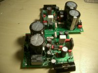
Hurray! I got my amps working tonight. I'm surprised that I didn't see the issue before and I'm surprised that nobody else caught the problem either. Its sort of obvious now that I know. Click on the picture to see if you can see the problem.
Look at the top-most leg of the LM3886 - Not even in the hole. Amazing how everything works when you have all the connections soldered.
The issue with the screeching sound seems to have been the heat sinks. Thanks to Troy for helping me out with those. I just got done playing the amps at a fairly loud volume for 45 minutes and they are barely above room temperature. My first impression is these sound great.
I'm using them with a Lightspeed Attenuator that I just built. There is some buzzing that I hear when the volume is turned up. I think its the Lightspeed, but I need to swap in another pre-amp to be certain.
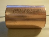
Assuming the buzz isn't in the amps, I want to swap out the C13 caps for something better that the Solen's I have in there now, secure the boards in the enclosures then close 'em up. I bought a couple of flavors of Obbligatos to try - 2.2 Copper Case Film caps, 2.0 Film Oil caps (big black cans), and 2.2 Tinfoil/Film caps. Just realized the tinfoil caps are rated at 250V, will that be an issue? Maybe I'll have to get some of those posts that ClaveFremen uses so I can compare. What do people think would be best?
An externally hosted image should be here but it was not working when we last tested it.
Look at the top-most leg of the LM3886 - Not even in the hole. Amazing how everything works when you have all the connections soldered.
The issue with the screeching sound seems to have been the heat sinks. Thanks to Troy for helping me out with those. I just got done playing the amps at a fairly loud volume for 45 minutes and they are barely above room temperature. My first impression is these sound great.
I'm using them with a Lightspeed Attenuator that I just built. There is some buzzing that I hear when the volume is turned up. I think its the Lightspeed, but I need to swap in another pre-amp to be certain.
Assuming the buzz isn't in the amps, I want to swap out the C13 caps for something better that the Solen's I have in there now, secure the boards in the enclosures then close 'em up. I bought a couple of flavors of Obbligatos to try - 2.2 Copper Case Film caps, 2.0 Film Oil caps (big black cans), and 2.2 Tinfoil/Film caps. Just realized the tinfoil caps are rated at 250V, will that be an issue? Maybe I'll have to get some of those posts that ClaveFremen uses so I can compare. What do people think would be best?
bluegti said:Hurray! I got my amps working tonight.
....
I bought a couple of flavors of Obbligatos to try - 2.2 Copper Case Film caps, 2.0 Film Oil caps (big black cans), and 2.2 Tinfoil/Film caps. Just realized the tinfoil caps are rated at 250V, will that be an issue? Maybe I'll have to get some of those posts that ClaveFremen uses so I can compare. What do people think would be best?
Well done!
250 V rating is not a problem (apart dimensions
), probably it sounds better than the 160V counterpart.The Obbligatos sounds very good but IMHO Mundorf Zns are better, more transparent.
In the meanwhile, since my personal components selection is definitive, I've removed sockets and soldered all.
Attachments
ClaveFremen said:
The Obbligatos sounds very good but IMHO Mundorf Zns are better, more transparent.
Are you comparing the sound of the Mundorf Zn's to the Obbligato copper case or to their Tinfoil/Film caps? I haven't read of anyone using their Tinfoil caps before. I just saw them and thought I would give them a try. From the description, it sounds like the Obbligato Tinfoil/Film caps are comparable to the Mundorf Zn's. They aren't much bigger than the Solens so I don't think size will be an issue.
I tracked down the buzzing problem to the Lightspeed Attenuator. I must admit that my soldering job was a bit rough on the perfboard I put together. And I'm not sure if I have things grounded entirely right so that will be my next project to debug on a different thread.
bluegti said:Are you comparing the sound of the Mundorf Zn's to the Obbligato copper case or to their Tinfoil/Film caps?
...
From the description, it sounds like the Obbligato Tinfoil/Film caps are comparable to the Mundorf Zn's.
The Obbligatos that I've tried are the copper ones, they're tin foil too.
If you listen Obbligatos and Mundorfs alone the Obbligatos seems better but when you compare both caps with DC couple the Mundorfs are clearly more transparent and Obbligatos a bit coloured (the famous 'analog' sound
).Attachments
Yet Another Transformer Hookup questions
I want to use center tap transformers to make the my_ref amplifier. All the pictures and sketches I have found on this thread show dual secondary transformers. Some posts talk about how the transformer needs to have 4 secondary wires. But a center tap transformer will only have three wires.
To hook up the dual secondaries two of the wires are spliced together and they go to the PGND connection on the pcb, the other two go to AC1 and AC2.
For a center tap transformer would it be correct to connect the center tap to PGND and the other two wires to AC1 and AC2?
For the Peter Daniel or BrianGT chipamp designs when one chooses to use a center tap instead of a dual secondary transformer, he must remove two diodes and install two jumpers on the bridge rectifier. Is this also required for the my_ref power supply? If not, could someone explain why not?
Finally it seems like very few people actually install fuses on the secondaries although it seems like it would be safer. Why is this so unpopular? Does it adversely affect the sound?
If I've missed the answers to these questions, I apologize. I tried hard to read all I could about it but couldn't find the certainty I am hoping for.
secondary fuses
Hi,
You may need to consider adding some form of DC detection and speaker isolation if the circuit does not like losing half the supply.
Hi,
what happens to the output offset if either one of the two secondary fuses are removed?few people actually install fuses on the secondaries although it seems like it would be safer
You may need to consider adding some form of DC detection and speaker isolation if the circuit does not like losing half the supply.
I had thought that fuses on secondaries was smart to. I rethought a few weeks ago and I agree with AndrewT its a really bad idea. Put the proper fusing before the transformer and you will be safe. You dont want one half of the secondaries to go out and still have half running. The amp wont like that either.
I am not sure with the other boards you mentioned here, but with the MyRefC I dont think there is any problem taking the center tap to power ground on one condition. Fire up your transformer and measure AC current from center to one secondary and then measure from center to the other secondary. If you get equal readings on each side then that means the amp will see the center as 0V and that is exactly power ground.
Remember to use your poor mans variac.
The AndrewT lightbulb tester.
If you have power supply issues or shorts in your amp or similar problems this will save your amp.
http://www.antiqueradio.org/dimbulb.htm
Uriah
It's not the Andrew T light bulb tester.
I read about it on this Forum and adopted it.
I happen to champion it's use, particularly since I found out how useful it has become once I learned to read the information it can give the builder and the protection it affords the test circuit/equipment.
I read about it on this Forum and adopted it.
I happen to champion it's use, particularly since I found out how useful it has become once I learned to read the information it can give the builder and the protection it affords the test circuit/equipment.
One Channel is not Working
Thanks for the replies.
I left out the secondary fuses although to be honest, I don't fully grasp the DC offset implications.
When I set the amp up for testing, one channel seems to be working fine, but the other one is silent.
The working channel clicks when starting. Both channels click when stopping.
Here are some pictures:
http://picasaweb.google.com/bmargot/My_refRevC02?feat=directlink
I'll review the thread as I recall someone else had a similar problem. But if anyone notices something amiss, I thank you for your comments.
Regards,
Blair
Blair and all,
Interesting that you post this problem tonight. I have been trying to get one of my "balls out" amps working for weeks, and I have not been able to find the problem. Replaced both chips and a few other parts, checked every solder joint with a magnifying glass, checked value of every component against the working amp, swapped power supplies, pulled out my hair, cursed a blue streak, sank into a blue funk, etc. I am absolutely desperate. I would PAY someone to fix this for me. I have another amp, but it sounds like crap compared to the My Ref. A $1200 amp, and I can hardly stand to listen to it after having heard this little wonder.
Good luck with your problem amp. Have you tried any troubleshooting? Examined all components for proper orientation? Checked solder joints?
Peace,
Tom E
one channel not working
I have done some basic checking with my dmm.
Both transformers have 122 VAC on the primary
Both transformers also measure 24.6 V AC between the center tap (green one) and the V+ and V- output wires (red ones)
Downstream of the bridge rectifier I measure 33.6 V DC between pgnd and the plus(+) and negative(-) output of the bridge.
On the working channel I measure 0.0 volts across the + and - of both PS capacitors C3 and C8
On the non-working channel I measure 33.6 V across C8, and 3.5 V across C3.
I am using a 4A 250V fuse on the power supply and it has not blown. The lightbulb in the dim bulb tester is not bright, in fact it does not even seem to be on at all.
I also checked the solder joints and redid some on the non working board. I removed C8 and verified the PCB solder pad was intact. My next step is to remove C3 and check the PCB solder pad under it.
The channel that works doesn't have any hum that I could detect.
Blair
Blair and all,
I would not suspect a lifted pad unless you did something weird while soldering. The boards are well made. I'm sorry I can't help you diagnose a problem based on the voltage readings, as I have only a very rudimentary knowledge of electronics.
One thing I have noticed while testing my boards, without power, is that some measured resistance values move upward in "steps" to the correct value on the amp that works, but read the correct value immediately on the amp that doesn't work. Does that signify anything to those who know their stuff?
I know this is DIY, but I have done all that I can by myself. I need a guiding hand.
Peace,
Tom E
- Home
- Amplifiers
- Chip Amps
- The new "My Ref" Rev C thread