Hi tnargs,
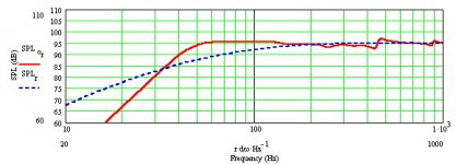
I ran a a couple of quick models starting with the dimensions for Fostex FE207e (and a few other 8" drivers). Using the port intended for the FE207e, the tuning was a bit too low, so I cut the port from 3" diameter by 3" long to 3" diameter by 0.75" long--which is to say, a 3" diameter hole in the 0.75" thick plywood; it looks pretty good. Attached is the SPL plot from MJK's MathCAD worksheets.
So the dimensions are:
L= 60"
S(o)= 4"x2.5"
S(L)= 12.25"x10"
Zd= 30"
Zp= 60"
Rp= 1.5"
Lp= 0.75"
Keep us posted on how it works out!
Cheers, Jim
Attachments
Philips 9710M [Troels measured] with more in room tuning flexibility/extended LF, especially if driven with a high output impedance or other driver needing a larger cab [~192 L/6.78 ft^3 net]:
L= 60"
S(o)= 35"^2
S(L)= 428.75"^2
Zd= 30"
Zp= 60"
density= 0.25 lbs/ft^3
Rp= 2.5"
Lp= 0.75"
GM
L= 60"
S(o)= 35"^2
S(L)= 428.75"^2
Zd= 30"
Zp= 60"
density= 0.25 lbs/ft^3
Rp= 2.5"
Lp= 0.75"
GM
Attachments
The T/S parameters I measured on my pair of ceramic magnet AD9710 were very close to that of Troels' Ticonal model. He seemed to be OK with the Philips recommended volume of ~40L; I found mine a bit too bloomy in ~50L. Interestingly enough, I though they did better in my Karlson K12 with ~36L of back-chamber. I guess the wider gain BW and location behind K-slot helped balance the notoriously Lowther-esque top-end.
They probably would sound great in a large QW design.
IG
They probably would sound great in a large QW design.
IG
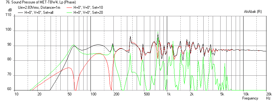
I just designed a Met for the Tang Band W4-1320sif inAkAbak. I don't know if it is any good. If someone with MJK can run a sim ton compare that would be appreciated.
The sim is here http://www.diyaudio.com/forums/full-range/223313-foam-core-board-speaker-enclosures-180.html#post3502315
The sim is here http://www.diyaudio.com/forums/full-range/223313-foam-core-board-speaker-enclosures-180.html#post3502315
Hi GM, that's a very interesting alternative, many thanks for your trouble.
I can see the extended LF on the SPL chart. Can you explain a bit more about how there is more in-room tuning flexibility with this design, please?
Greets!
You're welcome!
Well, what can you do with the smaller cab? If you tune it lower to better blend with the room’s gain curve you lose even more bass. Ditto damping it to improve transient response. Also, unless you design using measured specs of your drivers, the cab can be misaligned enough to require a lower tuning and/or excessive damping to smooth it out.
Last, but not least, is the impact that series resistance can have on a cab’s alignment due to effectively increasing the driver’s Qts, which can turn a nice flat sim into a ‘flabby’/’loose’ bass or even a ‘one note’ wonder in a worst case scenario when the Qts is already high.
With the seemingly too large cab, the obvious of course is the extra ~1/2 octave of bass extension that once damped or ‘used up’ due to series resistance can extend down to all but the lowest octave of some organ symphonies. This extra gain BW also tends to couple with the room better, especially larger ones where the 1st axial mode is low.
The extra acoustical loading inherently yields better dynamics, transient response, so once damped [if any extra is required] is technically superior in every way. Think sealed except with more LF gain BW.
Plus, you can always tune it up to match the smaller cab and get even more ‘toe tapping’ bass at a higher SQ due to all the extra acoustical damping.
Worst case is you have to reduce its net Vb some to keep from having to use excessive damping to ‘tighten’ it up, though I can’t recall that ever happening when starting with a T/S calculated alignment.
GM
Last edited:
Metronome theory question
Greetings,
A question, if I may. From what I picked up in MJK's Transmission Line Theory articles, specifically this one (page 9), if the transmission line is expanding, the resonant frequency of the fundamental goes up, while for a tapered (contracting) line, it goes down. It seems that the Metronome is an expanding taper, since the open port is on the bottom (larger) end, and therefore it would require greater length to produce the same fundamental resonance frequency, when compared with a straight or tapered line.
If the above is correct, wouldn't it make sense to have the bottom closed and the top open? Admittedly, this does allow introduction of dust, but wouldn't it also allow for a shorter body to get a given fundamental quarter wave frequency?
Any info appreciated.
Regards,
Martin
-----
Observe, predict, modify, repeat.
It expands but then is constricted - forming a mass loaded tapered quarter wave transmission line. The constriction pulls the freq lower. You may ask, why not taper the other way, well you can and people do - you see this in folded path contracting taper TL's. I think the benefit of having it larger at the bottom is twofold: (1) it provides stability for placement on the floor and looks good; (2) it reduces the peaks and dips seen in the tapering TL compared to an expanding TL. Also, having the bass port aimed at the floor provides a nice omnidirectional presence for the bass and reduces wall placement effects.
The metronomes by design are tapped mass-loaded quadratic horns. Reverse-taper (viz. narrowing to the terminus) pipes are inherently mass-loaded, which lowers Fb relative to the physical length whatever method is used to achieve it.
The truth is that in many cases you'll get equal (sometimes superior) performance from the same driver with a simple untapered MLTL, but that's not really the point: probably 80% of the metronomes built are for the aesthetic appeal as much as the performance, which when designed properly is usually perfectly solid.
The truth is that in many cases you'll get equal (sometimes superior) performance from the same driver with a simple untapered MLTL, but that's not really the point: probably 80% of the metronomes built are for the aesthetic appeal as much as the performance, which when designed properly is usually perfectly solid.
Last edited:
probably 80% of the metronomes built are for the aesthetic appeal as much as the performance, which when designed properly is usually perfectly solid.
I would agree.
The aim of my original Metronome concept was to:
a) update a Voigt quarter-wave horn for modern listening requirements.
b) make a speaker that looked stunning in a domestic environment.
c) get good sound.
I think it has succeeded on all three counts.
I have tried to refine the speaker over the years, but the basic concept and
execution has (fortuitously) turned out to be so darned right that improvements have been very hard to come by; it's just fiddling at the edges.
There have been one or two ideas from one or two folk about folding it as height seems to be an issue, but then it wouldn't be a Met, or a speaker that would appeal to so many women.
It's not a girly speaker, but a big part of its success has been in the area of domestic acceptability, and getting good sounding transducers past your partner/wife is one battle Met lovers don't have to think about.
")
I think it has succeeded on all three counts.
I doubt you'll get much disagreement.
If the above is correct, wouldn't it make sense to have the bottom closed and the top open? Admittedly, this does allow introduction of dust, but wouldn't it also allow for a shorter body to get a given fundamental quarter wave frequency?
Then it wouldn't be a metronome
Typically the height of the driver in a met is already kinda low. If you put the terminus out the top, the line would be shorter, moving the driver towards the floor. Further, with a decreasing cross-section taper, the Zd is typically closer to the closed end, so the driver would be even closer to the floor.
As an example, i had Scott design an ML-Voigt for some 4" Peerless, the sole purpose of going to the larger, more awkward build to raise the height of the drivers,
dave
Guys (or possibly gals too, ...),
Thanks for the speedy and informative replies. My follow-ups:
xrk971, could you expand on this? I don't doubt you at all, would just like a little more info. Does a contracting taper somehow increase the magnitude of the peaks and valleys in the frequency response? It would seem that conservation of energy across cross sectional slices through the line would indicate something like this. I might expect some non-linear features/interactions of the velocity field could lessen that, but not enough.
My initial thought was that since the end of the line is where the velocity changes are the highest, it would make sense to put that in the room where the velocity changes are the highest, far from any walls. But with those long waves, I suppose it matters far less.
Steve, as Scottmoose said, consensus agrees. I really like the aesthetics, and am hoping (with fairly solid confidence) that the sound is really good too. Will let you know after I finish building some.
planet10, with no top and a wide closed base on the floor, it would still look like a metronome. (Sarcasm noted, no worries.) I was asking in the spirit of learning about the design choices. But a squat little pyramid with an 8-12" speaker near the floor could be pretty cool too. And one could skew the angles of the tube (keeping S_o and S_l the same) so that the driver points up to the preferred listening position. Would make for a difficult speaker to move from room to room or house to house, but for the right room, it could be pretty sweet.
Again, thanks for the wisdom.
How about shapes? Triangular metronome - would allow for a slightly larger baffle on the speaker face, but with more complicated cutting and gluing. Pentagon shape would scream modern, but perhaps lose some of the elegance of the design (and be at least 25% more work, neglecting the more complex angles).
Are there any recommended treatments for the faces adjacent to the speaker to prevent immediate back reflections from coloring the sound? Dissipative linings, or angled surfaces?
Has anyone built a metronome with a Betsy-K? Has anyone done the calculations? Is this even a good candidate for a metronome build? I like the price, and the performance for the money is claimed to be good. Or does the much lower Q_ts of the Fostex 8" family work better in the met? Anyone modeled the Audio Nirvana 8" cast frame? That is probably the tippy-top of my price spectrum (although I've heard the bigger the better for drivers from AN).
And finally, one build question? How do you get into the narrow end to caulk the seams and do any woodwork? I could see getting 3 sides assembled fairly easily, but the last one and it's edges could be tough. Top and bottom on last makes sense, but how would one hide the screws for the top (not an issue for the bottom, clearly, a small corner join should solve it neatly)? Or is recommended practice to make the back removable with exposed screws?
Really liking this design more and more. Thanks again.
Cheers,
Martin
Thanks for the speedy and informative replies. My follow-ups:
(2) it reduces the peaks and dips seen in the tapering TL compared to an expanding TL.
xrk971, could you expand on this? I don't doubt you at all, would just like a little more info. Does a contracting taper somehow increase the magnitude of the peaks and valleys in the frequency response? It would seem that conservation of energy across cross sectional slices through the line would indicate something like this. I might expect some non-linear features/interactions of the velocity field could lessen that, but not enough.
Also, having the bass port aimed at the floor provides a nice omnidirectional presence for the bass and reduces wall placement effects.
My initial thought was that since the end of the line is where the velocity changes are the highest, it would make sense to put that in the room where the velocity changes are the highest, far from any walls. But with those long waves, I suppose it matters far less.
b) make a speaker that looked stunning in a domestic environment.
c) get good sound.
I think it has succeeded on all three counts.
Steve, as Scottmoose said, consensus agrees. I really like the aesthetics, and am hoping (with fairly solid confidence) that the sound is really good too. Will let you know after I finish building some.
Then it wouldn't be a metronome
planet10, with no top and a wide closed base on the floor, it would still look like a metronome. (Sarcasm noted, no worries.) I was asking in the spirit of learning about the design choices. But a squat little pyramid with an 8-12" speaker near the floor could be pretty cool too. And one could skew the angles of the tube (keeping S_o and S_l the same) so that the driver points up to the preferred listening position. Would make for a difficult speaker to move from room to room or house to house, but for the right room, it could be pretty sweet.
Again, thanks for the wisdom.
How about shapes? Triangular metronome - would allow for a slightly larger baffle on the speaker face, but with more complicated cutting and gluing. Pentagon shape would scream modern, but perhaps lose some of the elegance of the design (and be at least 25% more work, neglecting the more complex angles).
Are there any recommended treatments for the faces adjacent to the speaker to prevent immediate back reflections from coloring the sound? Dissipative linings, or angled surfaces?
Has anyone built a metronome with a Betsy-K? Has anyone done the calculations? Is this even a good candidate for a metronome build? I like the price, and the performance for the money is claimed to be good. Or does the much lower Q_ts of the Fostex 8" family work better in the met? Anyone modeled the Audio Nirvana 8" cast frame? That is probably the tippy-top of my price spectrum (although I've heard the bigger the better for drivers from AN).
And finally, one build question? How do you get into the narrow end to caulk the seams and do any woodwork? I could see getting 3 sides assembled fairly easily, but the last one and it's edges could be tough. Top and bottom on last makes sense, but how would one hide the screws for the top (not an issue for the bottom, clearly, a small corner join should solve it neatly)? Or is recommended practice to make the back removable with exposed screws?
Really liking this design more and more. Thanks again.
Cheers,
Martin
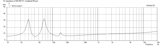
Has anyone built a metronome with a Betsy-K? Has anyone done the calculations? Is this even a good candidate for a metronome build? I like the price, and the performance for the money is claimed to be good.
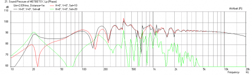
Here is a sim of the Betsy K in a Met that I came up with a while ago.
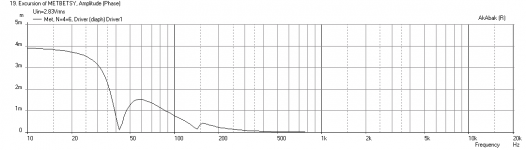
Design is: 8 in wide x 2 in deep at top, 26 in wide x 16 in deep at bottom, 60 in tall with driver at 23 in from top, 5 in dia x 2.25 in long vent at bottom, 3.5 in tall feet to let vent radiate out. Use stuffing from top to 2 inches below driver. Sim is for placement 60 in from wall 1 watt at 1 meter. Use 1.5 mH + 4 ohm in parallel for BSC.
It is a big speaker - the Met is not as compact as equivalent straight MLTL. Be careful with content below 40 Hz as excursion is large. Use only low power amp (< 5 watts).
Attachments
Converging Met with Betsy K
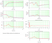
For grins, here is same speaker upside down but vent is at bottom and driver at 37 in from bottom. It is a converging TL rather than expanding, same volume. It goes much deeper but there are dips and peaks.
xrk971, could you expand on this? I don't doubt you at all, would just like a little more info. Does a contracting taper somehow increase the magnitude of the peaks and valleys in the frequency response? It would seem that conservation of energy across cross sectional slices through the line would indicate something like this. I might expect some non-linear features/interactions of the velocity field could lessen that, but not enough.
For grins, here is same speaker upside down but vent is at bottom and driver at 37 in from bottom. It is a converging TL rather than expanding, same volume. It goes much deeper but there are dips and peaks.
Attachments
FWIW, this is the Betsy K Metronome I did a few months back for the FH site.
H = 72in
St = 5in x 5in
Sl = 16in x 16in
Zd = 36in
Vent = 4in diameter x 0.75in long
Line cabinet throat, back & one sidewall 1in acoustic fiberglass or similar & adjust as required. It has a very slightly damped alignment; you can increase this via the vent or damping as you see fit.
H = 72in
St = 5in x 5in
Sl = 16in x 16in
Zd = 36in
Vent = 4in diameter x 0.75in long
Line cabinet throat, back & one sidewall 1in acoustic fiberglass or similar & adjust as required. It has a very slightly damped alignment; you can increase this via the vent or damping as you see fit.
Attachments
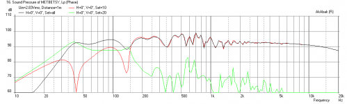
Does a contracting taper somehow increase the magnitude of the peaks and valleys in the frequency response? It would seem that conservation of energy across cross sectional slices through the line would indicate something like this. I might expect some non-linear features/interactions of the velocity field could lessen that, but not enough.
Not really; if anything, it can be the opposite, but this is circumstance dependent.
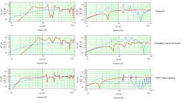
Assuming the same axial length and a constant internal volume, a narrowing pipe is inherently mass-loaded and has a lower Fb, with typically greater suppression of the harmonic modes. See attached. Three pipes, of the same physical length and total internal volume: untapered, expanding (horn) and narrowing (TQWT in its traditional parlance, i.e. the exact opposite of what is usually called a TQWT today). As you can also see, the horn has the widest gain BW, the TQWT the narrowest. I've left damping out to better illustrate the pipe behaviour -in all cases, these would need some damping & note these are not supposed to be in any way optimal, they're just illustrations.
Attachments
- Home
- Loudspeakers
- Full Range
- The Metronome