It's liberated. Attached is a pic of the motor from my second Mk2. I have two questions I want to ask to keep me on the right path.
1. Should I inspect the Torlon thrust pad for wear? And, even if no wear am I best off replacing the ball with a silicon-nitride ball. If I do, that I will replace the pad. Is there currently a reliable Torlon thrust pad provider?
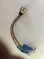
2. I would like to verify the motor wiring connections. The chassis connection is obviously a linear 12 pin connector.
I will essentially end up with a "2 box" turntable. The plinth with motor only and an everything else box with the chassis in it. it seems the logical thing for me to do is to make a connection from the 12 pin linear connector to that box's outside panel with a 12 pin round connector. Do a similar thing from the motor wires to the plinth back side surface. This will be fussy as it will require splices to the existing wires and clean method of running the wires and/or connector and a method to mount the connector. Then it will just be a matter to make a connector cable to the two box bulkheads. Got to get the motor connection part right. And finally, the power connection.
Thanks for the help.
Don

1. Should I inspect the Torlon thrust pad for wear? And, even if no wear am I best off replacing the ball with a silicon-nitride ball. If I do, that I will replace the pad. Is there currently a reliable Torlon thrust pad provider?
2. I would like to verify the motor wiring connections. The chassis connection is obviously a linear 12 pin connector.
I will essentially end up with a "2 box" turntable. The plinth with motor only and an everything else box with the chassis in it. it seems the logical thing for me to do is to make a connection from the 12 pin linear connector to that box's outside panel with a 12 pin round connector. Do a similar thing from the motor wires to the plinth back side surface. This will be fussy as it will require splices to the existing wires and clean method of running the wires and/or connector and a method to mount the connector. Then it will just be a matter to make a connector cable to the two box bulkheads. Got to get the motor connection part right. And finally, the power connection.
Thanks for the help.
Don
It's liberated. Attached is a pic of the motor from my second Mk2. I have two questions I want to ask to keep me on the right path.
1. Should I inspect the Torlon thrust pad for wear? And, even if no wear am I best off replacing the ball with a silicon-nitride ball. If I do, that I will replace the pad. Is there currently a reliable Torlon thrust pad provider?
2. I would like to verify the motor wiring connections. The chassis connection is obviously a linear 12 pin connector.
I will essentially end up with a "2 box" turntable. The plinth with motor only and an everything else box with the chassis in it. it seems the logical thing for me to do is to make a connection from the 12 pin linear connector to that box's outside panel with a 12 pin round connector. Do a similar thing from the motor wires to the plinth back side surface. This will be fussy as it will require splices to the existing wires and clean method of running the wires and/or connector and a method to mount the connector. Then it will just be a matter to make a connector cable to the two box bulkheads. Got to get the motor connection part right. And finally, the power connection.
Thanks for the help.
Don
I would advise inspecting the the bearing/thrust pad. It's also a good opportunity to flush the bearing sleeve and re-oil. I always replace the ball with SI3N4, every ball I have inspected shows signs of wear which will increase wear on a new pad. Plus the SI3N4 balls are far smoother and have better tolerance for roundness.
Unfortunately no-body I know of is making new thrust pads.
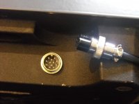
The motor connector wires are numbered. When I did mine I added some length to the motor wires by soldering additional wires to the connector end. The round 12pin connector will also have the pins numbered just transfer 1 to 1, 2 to 2 etc. The umbilical cord only needs pin to pin accuracy. I used the original motor connector on the electronic end to plug into the PCB.
With power I didn't do what @Bon did in placing them in an enclosure. My chassis sits on a shelf under the TT with the power supply sitting on the next shelf down or you could just sit power supply next to the chassis.
You may need to play with grounding. I had to ground the motor to the tonearm base to totally remove hum. I did this via a wire under the TT on one of the motor bolts to the underside of the tonearm mount so it was invisible.
Last edited:
Hi Don.2. I would like to verify the motor wiring connections. The chassis connection is obviously a linear 12 pin connector.
I will essentially end up with a "2 box" turntable. The plinth with motor only and an everything else box with the chassis in it. it seems the logical thing for me to do is to make a connection from the 12 pin linear connector to that box's outside panel with a 12 pin round connector. Do a similar thing from the motor wires to the plinth back side surface. This will be fussy as it will require splices to the existing wires and clean method of running the wires and/or connector and a method to mount the connector. Then it will just be a matter to make a connector cable to the two box bulkheads. Got to get the motor connection part right. And finally, the power connection.
Thanks for the help.
Don
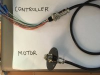
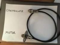
Here is how I wired my control box. Remove the terminal block and solder motor wires to a 12-pin male connector that will be plinth mounted. The motor wires should be long enough to reach if the plinth is not too deep.
Drill a hole for a 12-pin connector in the mkII rear chassis to be relocated in the control box. Attach a 12-pin connector with numbered wires to the re-attached terminal block for the control box circuit board. Carefully check the numbering and colours to verify it is wired correctly. I got the pre-wired 12-pin connector from eBay which saves some fiddly soldering and finding suitable wires. The connectors and plugs have numbered identification 1-12.
The 12-pin umbilical is again from eBay. I use 2m long to keep the control box away from the cartridge.
Attachments
Hopefully I haven't entered purgatory with my engine project. I tried getting the end cap off with a heat gun and warrjon's vice trick. Unsuccessful.
Good news, I think, is I took the retainer off and pulled the spindle out. Everything looked brand new. Couple pics attached. The thrust pad looks great. Haven't seen the ball (obviously). Zero contamination on the top side. Wiped the old oil off and re oiled the shaft and thrust pad and reinstalled the unit. I was surprised as it was cushioned as it got towards the bottom. Wouldn't go all the way in. Pulled it out again and looked at the shaft. My guess is that it was an air cushion as the oil was clearly distinguished on the shaft. Just left it for a couple minutes and it settled so I put the retainer back in place. Rotates perfectly.
Suggestions appreciated on getting the bottom cap off. Nervous about getting to hot or too forceful. Trying not to screw up a perfectly good motor.
Thanks,
Don
Hopefully I haven't entered purgatory with my engine project. I tried getting the end cap off with a heat gun and warrjon's vice trick. Unsuccessful.
Good news, I think, is I took the retainer off and pulled the spindle out. Everything looked brand new. Couple pics attached. The thrust pad looks great. Haven't seen the ball (obviously). Zero contamination on the top side. Wiped the old oil off and re oiled the shaft and thrust pad and reinstalled the unit. I was surprised as it was cushioned as it got towards the bottom. Wouldn't go all the way in. Pulled it out again and looked at the shaft. My guess is that it was an air cushion as the oil was clearly distinguished on the shaft. Just left it for a couple minutes and it settled so I put the retainer back in place. Rotates perfectly.
Suggestions appreciated on getting the bottom cap off. Nervous about getting to hot or too forceful. Trying not to screw up a perfectly good motor.
Thanks,
Don
I'd say that cap is good, I wouldn't replace it.
I use a mapp gas torch to heat the cap with aluminium covers over the vice jaws so they don't damage the cap. You need to apply enough heat to soften the Loctite. The issue could be someone has been there before and used permanent Loctite which will require more heat.
While you have the motor apart add some Blu Tack to the base of the motor housing to damp housing ringing. I have seen some motors that have damping added which looks OEM. I also remove the black aluminium cover on the top of the rotor, this is held in place with 3 bits of double sided tape. If you tap it you can hear it rattle.
Your bearing cap looks good.Hopefully I haven't entered purgatory with my engine project. I tried getting the end cap off with a heat gun and warrjon's vice trick. Unsuccessful.
Suggestions appreciated on getting the bottom cap off. Nervous about getting to hot or too forceful. Trying not to screw up a perfectly good motor.
Thanks,
Don
I bolt the motor to an angle bracket that is held in the vice and use my favourite wrench that can grip without excessive crush after applying a heat gun set to 400F. It takes an effort but will let go.
Attachments
One of the things that is very satisfying to see is the gauge of metal used for the Stator Bowl and the fact it is quite shallow in depth, as the Bearing Housing extends from it.
I have seen Stator Bowls almost twice this depth and pressed from a Metal not much thicker than 1mm, which is also the attachment for the Base of the Spindle Housing.
This type of design is begging for extra measures to be used to control flexion at the base of bowl.
The SP10 in comparison does seemingly not need as much concern showed for flexion occurring at the base of the housing, due to the substantial material used for the part, but is is not too difficult to achieve, so a worthwhile measure to adopt.
Thanks, Bon. Those flyers are cool. What do they call them. It is like a self locking Channel lock playerYour bearing cap looks good.
I bolt the motor to an angle bracket that is held in the vice and use my favourite wrench that can grip without excessive crush after applying a heat gun set to 400F. It takes an effort but will let go.
One of the things that is very satisfying to see is the gauge of metal used for the Stator Bowl and the fact it is quite shallow in depth, as the Bearing Housing extends from it.
I have seen Stator Bowls almost twice this depth and pressed from a Metal not much thicker than 1mm, which is also the attachment for the Base of the Spindle Housing.
This type of design is begging for extra measures to be used to control flexion at the base of bowl.
The SP10 in comparison does seemingly not need as much concern showed for flexion occurring at the base of the housing, due to the substantial material used for the part, but is is not too difficult to achieve, so a worthwhile measure to adopt.
My SP10's have used a locking collar to increase bearing rigidity for a few years now. Even though the motor housing looks strong it flexes. I measured the flex while I had the motor in the lathe.
It is an Automat wrench. Spring loaded with a very positive grip.Thanks, Bon. Those flyers are cool. What do they call them. It is like a self locking Channel lock player
They come in different sizes. They only have a limited range for each size so you need a selection.It is an Automat wrench. Spring loaded with a very positive grip.
Hi Warrjon, I 100% agree, that taking the time to discover a method to rigidly brace the Base of the Bearing Housing is an undertaking that will add to all other works being carried out.
Now you are experiencing the merits of adopting a Densified Wood as a Chassis, is there room to consider it as a material to mechanically attach to the Platter as you have dome with the Acetal.
There are Densified Wood Platters produced as well, I have seen one which I believe is for a Garrard 301.
Now you are experiencing the merits of adopting a Densified Wood as a Chassis, is there room to consider it as a material to mechanically attach to the Platter as you have dome with the Acetal.
There are Densified Wood Platters produced as well, I have seen one which I believe is for a Garrard 301.
Wow! Look at the Yellow wire close to the motor. Pinched to the point it almost broke completely through. Lucky it didn't short against part chafing it. This was a back up unit and never in regular use. I recapped and scoped it. It ran perfectly. Anyway, I wanted to show this. Not a perfect world.
Don
Don
Attachments
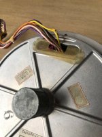
Looks like someone has had the motor out and pinched the wire when they reinstalled it.
You have a couple of options. Remove and replace the wire or cut the wire add heatshrink and solder it back together. Either will work fine. If you do solder it back together just make sure there are no spiky bits of solder that could pierce the heatshrink.
You have a couple of options. Remove and replace the wire or cut the wire add heatshrink and solder it back together. Either will work fine. If you do solder it back together just make sure there are no spiky bits of solder that could pierce the heatshrink.
I was surprised as it was cushioned as it got towards the bottom.
it is normal, more or less all the motors that I have overhauled have resisted the descent, a lot depends on the tolerances of the sleeve if it is worn or not, on the costance of maintenance in over 40 years of life and use of the motor, if used in the radio or in the studio or if used for private use.
The important thing is to let it go down without forcing anything.... after several minutes the pin went down completely.
Last edited:
it is normal, more or less all the motors that I have overhauled have resisted the descent, a lot depends on the tolerances of the sleeve if it is worn or not, on the costance of maintenance in over 40 years of life and use of the motor, if used in the radio or in the studio or if used for private use.
The important thing is to let it go down without forcing anything.... after several minutes the pin went down completely.
I'm servicing a motor and as part of that I always remove and check pad replace the ball, flush the bearing and re-oil. This motor took 2hrs to settle completely with the platter placed on it. Notably there is no scoring on the journal, this one looks new.
- Home
- Source & Line
- Analogue Source
- The Incredible Technics SP-10 Thread