Nelson Pass said:bon apetite
Thanks for the info, Papa.
Interested in 2A and 1A curves below 10W.
In general, I like to have 1 to 1.5A at somewhat high
junction temperatures on operational conditions.

jupiterjune said:
Are you saying I have too many output devices in my A-75????
JJ
If the A-75 had a reputation of blowing up, no one would build it. By having a small army of outputs, the amp is more likely to tolerate abuse.
You can decrease the number of output devices in the A-75 and retain the same total bias as long as you're careful with heat dissipation and such. As a fringe benefit, the cumulative Gate capacitance drops and the output becomes easier to drive.
Grey
jupiterjune said:devices in my A-75
The devices in the A75 likely have half the Ciss/Crss values of the ones used for these curves, don't you think the curves for the A-75 devices will be at a different distortion level?
The most interesting part is after the transition to Class AB, where the distortion level for the 0.25A curve still remains at 1/10th the level of a regular AB single compl. pair output stage.
Another reason NOT to use mosfets in minimum bias Class AB, good thing Mr Cordell is momentarily incommunicado.


Originally posted by Nelson Pass
This is a subjective call. Our five in-house listeners prefer the
sound at modest power levels when there is at least some
single-ended bias. However unless you're planning on full-power
single-ended Class A, you also need to have a substantial
push-pull bias to give a clean transition, otherwise the distortion
waveform suffers a glitch, and this is reflected in the sound.
The ratio of the two is pretty arbitrary, but I like to see single-
ended for at least the first watt or so.
Nelson,
Thank you for the illumination.
Graeme
Re: Re: The Importance of Being Biased
1) The X axis is rms watts. Peak is necessarily twice that.
2) Yes, it doesn't, and that's part of the point. You don't see
a big crossover notch and then suddenly in Class A the distortion
is gone. There is a smooth transition in character over the
whole power range.
3) At high bias the crossover distortion is there, but it is
disguised in the lower harmonics.
4) Manufacturers do not advertise bias because their real
bias numbers are pretty small compared to what they think
the consumer expects. They don't use more bias because it's
costly in terms of harware.
audiorob said:
Ok, just to make sure I understand, the X scale is peak watts, and
the Y scale is distortion, right?
If so, and if we leave Class A at 0.125 watts peak, then the graph
doesn't show much information about distortion while in Class A
operation, does it? Is the point that there is no discontinuity (ie:
there is a nice smooth curve) in the graph at the point where we
transition from Class A to Class AB? Or is there a more profound
meaning that I don't yet understand?
So, if we are have left Class A (by which I mean that the transistors
are not conducting for the full 360 degrees), and we have no feedback,
where is the crossover distortion due to the lag or phase shift of the
transistor switching into conduction? (I really hope I'm using the right
jargon here, but I admit I'm struggling).
Also, aside from dealing with amplifier heat issues, if increased bias
current reduces THD, why aren't manufacturers having a "numbers
race", publishing their amp's bias current figure?
1) The X axis is rms watts. Peak is necessarily twice that.
2) Yes, it doesn't, and that's part of the point. You don't see
a big crossover notch and then suddenly in Class A the distortion
is gone. There is a smooth transition in character over the
whole power range.
3) At high bias the crossover distortion is there, but it is
disguised in the lower harmonics.
4) Manufacturers do not advertise bias because their real
bias numbers are pretty small compared to what they think
the consumer expects. They don't use more bias because it's
costly in terms of harware.
lumanauw said:Bob Cordell use low biased mosfets, but with EC. It would be very interesting to see low biased mosfet EC vs mosfet classA graphs
It would be interesting if Bob applied EC to Class A. I have
encouraged him to think about that, but I do expect that the
improvements offered by EC would be less dramatic under
those circumstances.
Mr. Pass, I tried EC and classA, and they do sound different. ClassA sounds more relaxed. I know there are many different factors (like different damping factor, for example).
But this has make me think. The "sound of classA" is not entirely because of the continuous gm over crossover region (or the absence of crossover distortion), but I think it is also because of the less ripple in the power rails. ClassA draws constant current, and this less ripple (that will be injected to the small signal parts or coming to the output via Cgd (or Cbc) of the output stage.
While EC can maintain no crossover distortion, it cannot maintain small ripple in the power rails. Am I thinking right about this?
Mr. Pass, in your younger age, maybe you have thought alot about the essence of what is happening in classA mode (and come with patent #5,343,166). Have you thought about how to get the essence of continious gm, but without the heat of classA (candidate of Pass' patent #8, maybe?)
Hartono said:continious gm
What is the continuous gm?
Do you mean continuous constant gm?
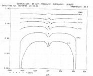
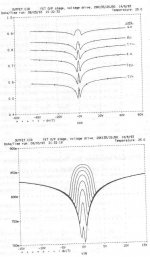
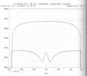
I cannot find the data of the bias current of those graphs. It is from DSelf book, but it seems that he believes in the voltage drop accross RE degeneration more than the bias current.
This graph is from the exactly same cct, the upper is when the output is classA (biased at 1.6A) and the lower is at the "optimally biased classB"
The classA graph has relatively steady gain between 0.980-0.985, while the lower is very curved (especially around 0V) and the gain is always less than 0.970
It's a good clue why Papa likes classA
Attachments
- Status
- This old topic is closed. If you want to reopen this topic, contact a moderator using the "Report Post" button.
- Home
- Amplifiers
- Pass Labs
- The Importance of Being Biased