Either I don't understand or your numbers can't be correct. The most loss that I have seen from foam is about 3 dB and its usually more like 2 dB. The HF fall in a CD device because of the CD and this adds another 6 dB or so resulting in about a 10 dB boost required at 10 kHz to yield a response that is flat to 1 kHz. But only a few dB of this is foam, the rest is the fact that the energy is going over a much larger polar angle at HF than it is a typical system.
Earl,
Remember how some people didn't believe that HOMs existed, because they were difficult to measure? And subjectively, I have personally noticed that the foam makes a more audible improvement in horns than in waveguides.
My hypothesis is that bad horns generate more HOMs, and therefore the foam is more effective on bad horns. And the response plots reveal the story - there's a greater attenuation in a bad horn than in a waveguide, because a greater percentage of the horns energy is due to HOMs.
One way to visualize this is to compare it to a device where distortion is a significant percentage of output, for instance an amplifier that is being driven to it's limits, and a significant chunk of the output is harmonic distortion.
Anyways, that's the hypothesis. Measurements will tell the whole story. To demonstrate my hypothesis, I will measure four devices:
- A HOMster - a horn that's far far from ideal. The USD horns are an excellent example of a horns that's severely undersized, and whose dimensions are skewed. (IE, it's height been reduced by about 80% from the ideal.)
- A HOMster that's been treated - to demonstrate the effect of diffraction treatment on a horn that's far FAR from ideal.
- An OS waveguide - to demonstrate how a properly sized waveguide behaves, loaded with the exact same compression driver.
- An OS waveguide that's been treated - to demonstrate the effect of diffraction treatment on a properly sized waveguide.
Stay tuned for the results.
Have you considered breaking up HOMs with absorptive septums (balsa or foam??)
rather than non-directional foam full plug that absorbs -2dB of the dominant mode.
I'm not suggesting a cellular horn of exponentially shaped septums, just a plain
conical waveguide divided by thin flat septums. Where cutoff frequency of the
lowest possible HOM has been pushed slightly above the audible limit. Does this
make any sense???
Last edited:
It's interesting to consider that at many frequencies, an untreated horn has more energy from reflected energy than from the primary wavefront. No wonder they can sound so poor!
How can you conclude that??
How can I conclude that an untreated horn has more energy from reflected energy than from the primary wavefront?
With a bit of math:
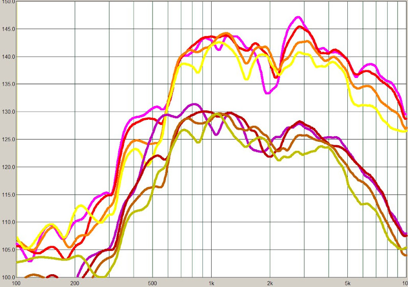
In the pic above, we have a graph of the same horn. One is fully treated, one is not. The bottom graph is shifted by ten db. At 4khz, we see that the treated horn is 6db less efficient. This demonstrates that at least 50% of the energy at 4khz in the untreated horn is due to reflections. The difference is particularly noticeable in the purple curve, which is 45 degrees off axis. At 2800hz there is an extraordinarily strong reflection, and the untreated horn is fully 10db more efficient at that frequency.
Keep in mind that this horn would not behave in such a strange manner if it was properly sized. Due to the strange dimensions, it's all but impossible to simulate in software, and conventional horn theory just isn't designed to predict how this thing will behave.
It is my hypothesis that this horn has particularly severe HOMs, and that is why the diffraction treatment is so noticeable in the plots.
As noted in the previous post, I intend to explore if that is true by comparing it to a waveguide.
You wanna break up HOM in a really bad horn??? Plug up a Karlson.
Gonna need even more Eq I think... They used to Laquer inside of
them things to deliberately sustain said reflections.
Wide waveguide, parallel walls, what better worst case can you ask?
Though it may be a HOM that builds up behind the central slot that
makes the thing work at all, foam might just kill it completely...
Last edited:
Have you considered breaking up HOMs with absorptive septums (balsa or foam??)
rather than non-directional foam full plug that absorbs -2dB of the dominant mode.
I'm not suggesting a cellular horn of exponentially shaped septums, just a plain
conical waveguide divided by thin flat septums. Where cutoff frequency of the
lowest possible HOM has been pushed slightly above the audible limit. Does this
make any sense???
I've considered that.
A conventional horn that plays to 150hz needs to be very big. For instance, the length should be at least 23 inches, and the mouth needs to be very large... A diameter of 92 inches isn't "out of the question."
Now we can reduce the mouth size, but the frequency response goes to hell. The typical solution is to find a "happy medium", where ripple isn't too bad, and the box size isn't too big.
Danley stumbled across a novel solution to the ripple problem, which is basically to "tune" the ripples to smooth out the response. It works quite well for subwoofers, but not so great at high frequencies.
The reason that it doesn't work at high frequencies is that a "notch" is introduced into the passband, and that sets the upper limit.
For over three years I've been trying to figure out how to get a tapped horn to play full range, and I think that I'm very close now.
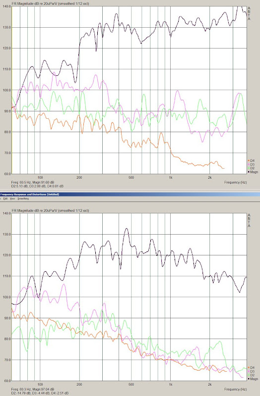
- This horn's response is +/- 3db for three octaves, from 200hz to 1600hz.
- Above 500hz, the horn's distortion is over 40db below the fundamental. To get this kind of performance in a sealed box requires very expensive woofers. There are other horns with comparable distortion performance, but none that are this small.
- Probably the most impressive aspect of this horn is that it has the best of both box types. It has low frequency performance that's comparable to a sealed box, a box size that's competitive, but distortion that's much lower, with a wider bandwidth than a tapped horn.
Like the HOMster, the device above has lots of HOMs. The difference is that this device is generating reflections in a very calculated manner, and then using polyfill to "soak them up." So you wind up with the low distortion of a horn, in box which would normally be far too small. (The entire enclosure is less than two liters.)
I've seen that shape before... What was it "Jensen Laboratory Standard"???
Drawing ripped from Radio Electronics April 1955 pg 31.
"Horn Type Speaker Systems" by George L. Augsperger
There was a PDF of that article floating about recently,
but I've lost track of the link.
The text of the article describes just what you were saying.
Drawing ripped from Radio Electronics April 1955 pg 31.
"Horn Type Speaker Systems" by George L. Augsperger
There was a PDF of that article floating about recently,
but I've lost track of the link.
The text of the article describes just what you were saying.
Attachments

Last edited:
The Lab Standard was model RS-100, there was also an Imperial PR-100.
I'm having trouble digging up anything more informative...
I'm having trouble digging up anything more informative...
OK, not the link I was looking for, but plenty of infos here...
The second one takes a while to load.
http://www.geocities.ws/footstony/audio54.pdf
http://www.superbadcat.com/jensen/imp_diy.pdf
The second one takes a while to load.
http://www.geocities.ws/footstony/audio54.pdf
http://www.superbadcat.com/jensen/imp_diy.pdf
How can I conclude that an untreated horn has more energy from reflected energy than from the primary wavefront?
With a bit of math:
In the pic above, we have a graph of the same horn. One is fully treated, one is not. The bottom graph is shifted by ten db. At 4khz, we see that the treated horn is 6db less efficient. This demonstrates that at least 50% of the energy at 4khz in the untreated horn is due to reflections.
The foam also affect the direct wave, so this is unconclusive.
You should mesure the attenuation caused by the foam plug when a wave passes through it once (direct wave), and conpensate your fuly threated curve to really show reflections attenuation. Only then you could deduce the amount of energy from reflections.
Last edited:
Have you considered breaking up HOMs with absorptive septums (balsa or foam??)
rather than non-directional foam full plug that absorbs -2dB of the dominant mode.
I have considered this as conceptually it makes sense. Its the implimentation that is problematic. Compared to foam its a nighmare to invision how to make such a thing.
My hypothesis is that bad horns generate more HOMs, and therefore the foam is more effective on bad horns.
I would tend to agree with that. When the house is very dirty just picking up a few things makes it look a lot better. But a clean house is much harder to improve upon.

I'm going to try some reticulated foam (guy just wanted rid of it at the pet shop, apparently the size was wrong. Score, $1.25 for each piece (about a 5.25" dia cylendar, 1.25" tall) and edge termination on some JBL 2370s.
Earl, would it be correct in assuming that much of the coloration of a diffraction slot itself could be attenuated by the foam? I'd think that reflections back towards the diaphragm would be a significant part of the issue. I'm planning to cut it as well as I can to match the throat profile and extend past the diffraction slit, am I likewise correct in assuming that it can be rather "rough" cut? Should it be fastened to the sidewalls?
I'm also assuming that we'd see a far less significant effect from roundovers on the sidewalls, where the horn flare pretty smoothly transitions into a flat front baffle.
I'm planning to use Aitwood Anderson International - StoreFront for the roundover transitions.
I've seen those corner pieces. They look very attractive.
I am inclined to believe that the foam would help any horn and the worse that it is the more that it would help. You can probably rough cut it and just hold it in place with compression.
I am inclined to believe that the foam would help any horn and the worse that it is the more that it would help. You can probably rough cut it and just hold it in place with compression.
I'm also assuming that we'd see a far less significant effect from roundovers on the sidewalls, where the horn flare pretty smoothly transitions into a flat front baffle.
I's been my subjective experience with my Unity's, that the throat area is most important. I wonder if certain frequencies are more noticeable in this regard.
I originally filled the horn with foam - from the phase plug of the driver to the mouth. I found that I could take out the front third, or so (as measured by depth), without reducing the apparent effect. That front third makes up the bulk of the foam (like the bottom of a pyramid). What I care about are specific reflections that create echos (HOM?). Sounds like, well, like a horn. I don't like the speakers to sound like someone is singing into a metal trash can (even though the effect was slight with the untreated waveguide). Don't like back loaded horns for that same reason.
I never spent much time thinking about a generalized sense of harshness, so I don't know if that's something distinct from the perceived echos, or whether it's just different frequencies that affect our perception differently. I would guess that there is some higher frequency cut-off where an echo no longer sounds like an echo. I would think that it's related to frequency as well as the amount of delay, and probably the number of reflection cycles and rate of decay - and some relationship between all those (and probably more) factors. Pretty complicated, I'd guess.
Sheldon
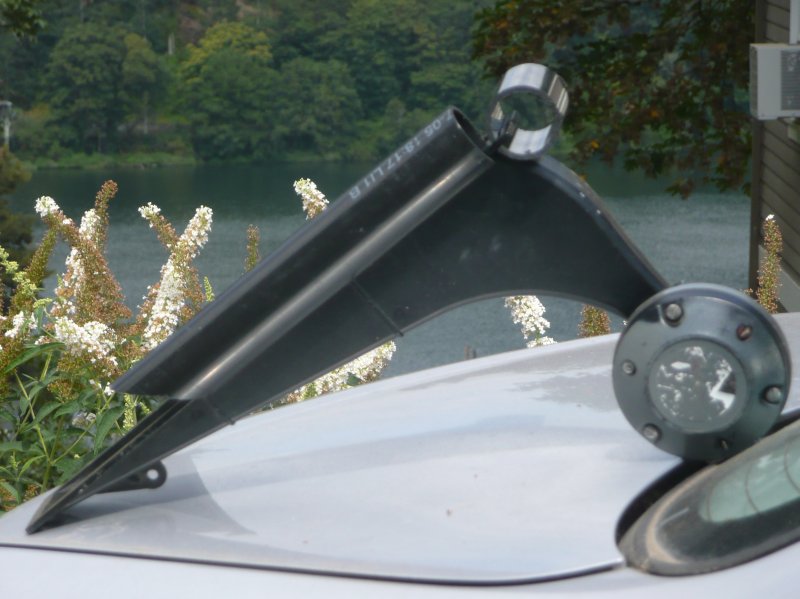
Tried something stOOpid that didn't work, but thought I'd share all the same.
NXT exciter near the throat of my StyroSmith. Does not appear to have any
use or abuse as a unity driver in this application. Maybe its just septums of a
Smith horn damp out the flex modes? Certainly got along plenty well enough
with large flat panels of the same exact pink extruded polystyrene foam.
Proabably comes as no surprise to those who know, that this shouldn't work.
But I was dumb enough to try it anyway. Figured I'd save other dummies the
five bucks price of admission to repeat the experiment.
Last edited:
I've seen those corner pieces. They look very attractive.
I just purchased 2 of the 2" radius 8" lengths. Shipping cost to NY was the price of a single piece. It also shipped today. Not bad at all!
Rob🙂
I just purchased 2 of the 2" radius 8" lengths. Shipping cost to NY was the price of a single piece. It also shipped today. Not bad at all!
Rob🙂
I'm lucky enough to live close by, so I don't pay any shipping

Patrick Bateman, Roundover
Hi,
Glad to read some else thought of roundovers, I thought I was alone!
I've been using 4" PVC white pipe cut in half length ways for my roundovers.
Cut to fit the edge lengths of my mid range box (ATC soft dome) and it smooths out a roughness in the sound from diffraction.
Also use it on my tweeter clear plastic baffle for similar good effect.
I use clear 2" wide heavy duty packing tape to tape on the pipe.
Looks like crap but sounds good, not great.
In your horn you might also try using wool from an old sweater or jacket to line some part of your horn. Different foams, wool, felt, etc work at different frequencies. Wool felt is supposedly good for higher frequencies.
Have fun!
Attachments

The roundover on The HOMster really made an improvement. But what if we filled the horn with foam? And while we're at it, why don't we add a vertical roundover?
So I chopped up about fifty cents worth of PVC pipe, and added about a dollar worth of 30 ppi reticulated foam inside the horn.
Geddes uses reticulated foam to damp the sound which doesn't travel down the axis of the horn. The way that the foam works is that it absorbs the axial wave once, but the reflections inside the horn are absorbed many times. (Since the reflected energy is reflected back down the throat, off the walls, off the mouth, etc...)
Also, just to be a complete lunatic, I put a *full* roundover on the horn. In other words, the roundover extends *into* the mouth. Because the top of the horn is baffled, my hypothesis was that this wouldn't affect the low end dramatically. Besides, if half a pipe is better, how about a full pipe?
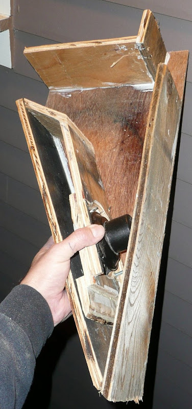
Here's what the horn looks like for these measurements:
Note the roundover on the sides *and* the mouth.
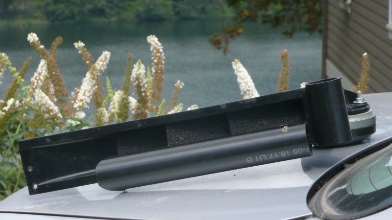
The horn has been filled with 30ppi reticulated foam. The 2" PVC pipe extends all the way into the mouth now. In the previous measurements, it was a half pipe, duct taped to the bottom of the horn.
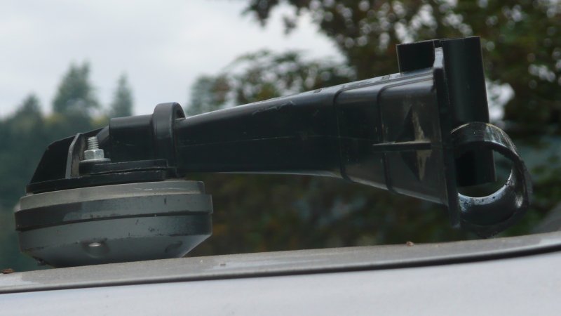
In the side view you can see this is a REALLY small horn. That's a Radian compression driver.
Of course, this is outside the car. The polar measurements were performed inside the car.
And speaking of polar measurements, here they are. The untreated response is at the top. After the second stage of treatments, I measure the horn at the same voltage level. In the graph the second set of measurements were lowered by 10db.
The HOMster with a horizontal roundover, a vertical roundover, and stuffed with reticulated foam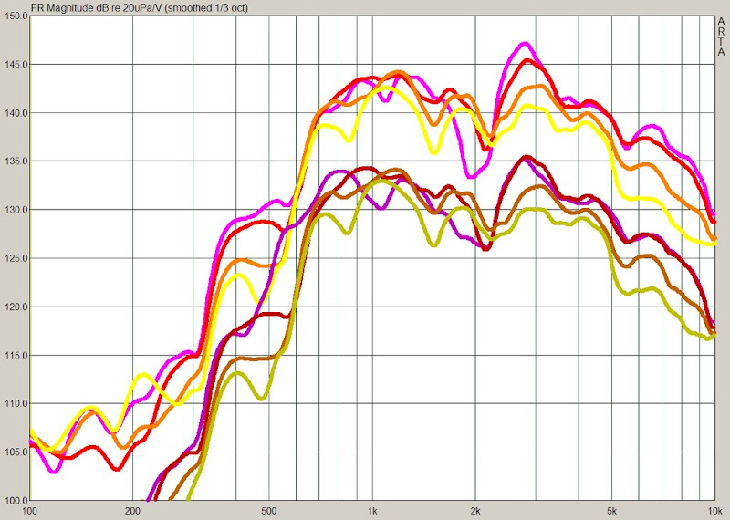
The HOMster with a roundover
What do you think? Here are my thoughts:
- The 0 degree (purple) and the 15 degree (red) curve are virtually indistinguishable now. They track each other within 2db from 1200hz to 10khz. Remarkable for such a funky horn! And a dramatic improvement over the untreated horn.
- The untreated horn has a nasty dip and a peak at 1800hz and 2800hz, respectively. When you have a peak and a dip so close together, it's a challenge to treat with an EQ. But that didn't stop people from trying. These horns were used in dozens of "sound off" cars, where they were frequently paired with expensive Rane equalizers, modified for use in the car. The equalizers alone cost hundreds of dollars, and modding them for the car increases the cost. Now look at the treated horn. Where's the peak and the dip?
- The foam and the roundover has tamed the peak and the dip. Even better, what remains of the dip is fairly consistent on axis and off, and it's shallower and wider. This means that the dip can be treated with EQ (finally!)
- There's a dramatic reduction in the output level. It's down 3db at 1khz, but almost EIGHT db at eight khz. I think this is enlightening, because it illustrates that a significant percentage of the horn's output is being damped by the foam. I have stuffed an OS waveguide with foam, and measured it, and the reduction in SPL wasn't as dramatic as this. I believe this proves that the HOMster has more HOMs than an OS waveguide.
- The response curves of the treated horn fit in a tighter window. For example, the curves of the treated horn fit inside a window that's approximately five db wide. The response of the untreated horn fits inside a window that's eight db wide.
- Without a doubt, the most notable difference is that the treated response is consistent. The response of the untreated horn is consisten for about an octave, but then the off-axis response is subject to wild swings above 1500hz. Psychoacoustic research tells us that this is exactly where we DON'T want wild swings, since we're so sensitive to frequency response discrepancies above 1khz.
In summary, the objective measurements demonstrate that a small investement in PVC pipe and foam can reduce diffraction a great deal. And reducing diffraction improves the consistency of the on and off axis response. I am not able to measure HOMs, but I know what they sound like. In the next post, I'll describe the subjective improvement of these tweaks.
Actually, I have been following a similar path to yours here, playing with what improvements may be available. It looks to me like you have actually made your horn worse, by obstructing the mouth with the second piece of PVC. This would dramatically increase HOMs, not reduce. The arrangement you used on the side of the horn is vastly preferable in smoothing the transition from loaded to unloaded.
- Home
- Loudspeakers
- Multi-Way
- The HOMster! (or How I Learned How to Fix a Horn)