Thank you, Lynn. It makes me feel a little better to know that an expert has had similar mishaps.
Where I get flummoxed is trying to check the resistance in certain areas b/c it shows as 0 before the caps are charged and then it rises while they charge with even the small voltage from the DMM.
I thought one of the current limiting resistors for the LED was shot, but when I removed it... it tested fine.
At the moment... it seems that one of the bleeder resistors failed open, so I'm removing it to check.
I ran a quick and dirty diode check with a DMM for all 4 diodes / 8 sections for each rail, (they're double diode packages best I can tell with my limited understanding) and I'm trying to digest those results.
If anything... it will help with my troubleshooting skills.")
Where I get flummoxed is trying to check the resistance in certain areas b/c it shows as 0 before the caps are charged and then it rises while they charge with even the small voltage from the DMM.
I thought one of the current limiting resistors for the LED was shot, but when I removed it... it tested fine.
At the moment... it seems that one of the bleeder resistors failed open, so I'm removing it to check.
I ran a quick and dirty diode check with a DMM for all 4 diodes / 8 sections for each rail, (they're double diode packages best I can tell with my limited understanding) and I'm trying to digest those results.
If anything... it will help with my troubleshooting skills.
This makes it possible to reemphasize the role of gm in matching the NFET to the PFET and concentrate on a different parameter(s).
View attachment 1298264
If you make Rx a trimpot, you can trim (out) H2 with a distortion analyser.
Patrick
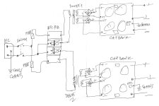
Re: PSU boards... ZM (the great) generously provided me with the gerbers to have his "HA!"-cap-bank boards made by myself. Now I got some 8 spare PCB of this, if anyone would like to make use of it. (I would ask a few $ for them though)
ZM's HA!
What I did with it
ZM's HA!
What I did with it
Thank you @lhquam also how critical are these odd value resistors in the front end just trying to see if I can use the parts from my stash
RF2 1 x 43.2k 1/4 watt 603-MFR-25FBF52-43K2
RF3 1 x 511k 1/4 watt 603-MFR-25FBF52-511K
RF4 1 x 169k 1/4 watt 603-MFR-25FBF52-169K
Thanks
RF2 1 x 43.2k 1/4 watt 603-MFR-25FBF52-43K2
RF3 1 x 511k 1/4 watt 603-MFR-25FBF52-511K
RF4 1 x 169k 1/4 watt 603-MFR-25FBF52-169K
Thanks
@manniraj,
On page 9 of the build guide, Lynn has provided details on how resistors RF0-RF4 affect not only the input impedance, but also the overall gain by manipulating the amount of feedback. I suggest you go through the computations with the resistors that you have in your stash to see how these values change and to see if they are compatible with your own goals of closed loop gain and input impedance.

Best,
Anand.
On page 9 of the build guide, Lynn has provided details on how resistors RF0-RF4 affect not only the input impedance, but also the overall gain by manipulating the amount of feedback. I suggest you go through the computations with the resistors that you have in your stash to see how these values change and to see if they are compatible with your own goals of closed loop gain and input impedance.
Best,
Anand.
Last edited:
They are no that critical. Slightly different values will modify the gain and global feedback factor a bit, but if the same values are used for each channel you will not have any problems.Thank you @lhquam also how critical are these odd value resistors in the front end just trying to see if I can use the parts from my stash
RF2 1 x 43.2k 1/4 watt 603-MFR-25FBF52-43K2
RF3 1 x 511k 1/4 watt 603-MFR-25FBF52-511K
RF4 1 x 169k 1/4 watt 603-MFR-25FBF52-169K
Thanks
This is a very serious development; congratulations!
A question: To what extent does a non-switching Class AB output stage reduce the odd order harmonics on an FFT for the entire frequency and output levels vis a vis a conventional, high feedback Class AB?
With others over a few years we have found that non-switching is a terrific idea, but in reality the odd order reductions, the 'machine tones', are small. I have done AB and A amps and found that there are subjective differences in presentation however and I wonder if we are missing something here. There might be something else the ear hears but we do not measure.......
HD
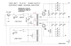
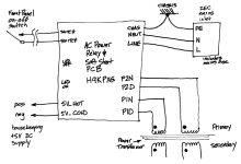
I have a little follow-up on the PSU-discussion: I intend to build a FW-style regulated PSU, in dual mono (1 independent PSU per channel), like in the attachment, but with 1 NTC ground-lift per channel... As far as I could follow the discussion, this shouldn't be an issue I presume?
Attachments
What circuit will you add for regulation?I have a little follow-up on the PSU-discussion: I intend to build a FW-style regulated PSU….
I have a little follow-up on the PSU-discussion: I intend to build a FW-style regulated PSU, in dual mono (1 independent PSU per channel), like in the attachment, but with 1 NTC ground-lift per channel... As far as I could follow the discussion, this shouldn't be an issue I presume?
common IEC, common switch, then everything else separate per channel
Note that with common IEC (including common chassis ground) and common switch, the fuse for each channel should be located after the switch, unlike the schematic which shows the fuse between the IEC and switch for the stereo configuration.
If you wish to have a switch for each channel, then the fuses may be located between the IEC and switches.
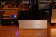
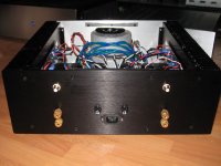
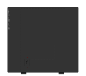
I built a dual mono amplifier with a switch for each channel. It's one extra step at turn-on and turn-off but it is handy and I like the look.
Attachments
Ahem. Now that you're asking, I (probably again) confused terminology? I will use a conventional 24VWhat circuit will you add for regulation?
@Ben Mah Thank you for the heads-up. Although a dual-mono-dual-switched solution is cool, there will be one switch and one softstart-board triggering both PSUs. I'm not sure where this will lead me to / where the fuses will be, but I'll use Mark's H9KPXG Softstart… (Even if Mark's sketch indicates the fuse before the switch—integrated in the inlet—I am confident it will be appropriately and entertainingly
answered…).Attachments
In other words, no, it’s not the R21!What circuit will you add for regulation?
💪Best,
Anand.
- Home
- Amplifiers
- Pass Labs
- The Holy Grail Follower Output Stage