MJL21193
MJL21193
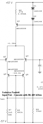
What do you think about this cascode method !!! ???
Just select one suitable resistor to get the cascode voltage you want.
A little hook only.
We need a rather precise bias current for LTP pair.
So is perfect for CCS biased LTP.
I find it simple & very elegant.
I have no doubt it is very good (the italian designer is one pro).
Enjoy
MJL21193
What do you think about this cascode method !!! ???
Just select one suitable resistor to get the cascode voltage you want.
A little hook only.
We need a rather precise bias current for LTP pair.
So is perfect for CCS biased LTP.
I find it simple & very elegant.
I have no doubt it is very good (the italian designer is one pro).
Enjoy
Attachments
no the base potential is related to supply
from pure technical side, it is not easy to see any benefit
compared for example with the MJL21193 CCS cascode connected to LTP emitters
anyway, it may be interesting to try what kind of performance differences this gives
the designer, as said, is wellknown for highly regarded amplifiers
something good must be in this .. or
What happens if the beta of Q4 and Q5 changes by, say, a factor of two (maybe by substitution of parts)? What is the impedance looking into the emitters of Q4 and Q5? Is it larger or smaller than R7? Does this defeat the purpose of a common-base amp?
I originally thought you may have posted this circuit as a joke.
I originally thought you may have posted this circuit as a joke.
lineup said:no the base potential is related to supply
from pure technical side, it is not easy to see any benefit
compared for example with the MJL21193 CCS cascode connected to LTP emitters
anyway, it may be interesting to try what kind of performance differences this gives
the designer, as said, is wellknown for highly regarded amplifiers
something good must be in this .. or
You are right I don't see any benefit in the discussed circuit.
I have not seen MJL's cascode, but are you sure the cascode is on the emitter of the LTP, and not on the collector of the CCS?
I know it will look the same on the schematic, but anyway if it's a cascode there it's on the CCS and not on the emitter of the LTP.
The first thing I would do is to place a CB (Cascode) on the collector of the LTP., and even include a correction circuit.
Stinius
Re: MJL21193
Why not? I like the simple solutions.
OTOH, the voltage divider will give more precise and selectable results without much added complexity.
lineup said:MJL21193
What do you think about this cascode method !!! ???
Just select one suitable resistor to get the cascode voltage you want.
Why not? I like the simple solutions.
OTOH, the voltage divider will give more precise and selectable results without much added complexity.
andy_c said:What happens if the beta of Q4 and Q5 changes by, say, a factor of two (maybe by substitution of parts)? What is the impedance looking into the emitters of Q4 and Q5? Is it larger or smaller than R7? Does this defeat the purpose of a common-base amp?
I originally thought you may have posted this circuit as a joke.
I agrre as I have stated before I don't see any usage of this circuit.
Stinius
stinius said:
I have not seen MJL's cascode,
Post #332
MJL21193 said:
Post #332
OK I have seen it now, but that's an ordinarry cascode and it's on the collector of the LTP and not the Emitter as Lineup sayd.
Stinius
I've seen a similar cascode to what MJL suggests in post 337 used on the AEM9000 amp by Tillbrook, but with a zener in place of the resistor used from cascode base to the LTP current sink.
I'm debating this as I have some 2SK139's from the Teac that might be worth a look.
I'm debating this as I have some 2SK139's from the Teac that might be worth a look.
jaycee said:I've seen a similar cascode to what MJL suggests in post 337 used on the AEM9000 amp by Tillbrook, but with a zener in place of the resistor used from cascode base to the LTP current sink.
I'm debating this as I have some 2SK139's from the Teac that might be worth a look.
The LED is just a voltage drop, so a zener would do the job.
Stinius
stinius said:
OK I have seen it now, but that's an ordinarry cascode and it's on the collector of the LTP and not the Emitter as Lineup sayd.
Stinius
Yes, I think that lineup might have miss-worded it. The scheme he suggested was also an ordinary cascode.
jaycee said:
I might have to lay out a PCB
The more, the merrier
Besides, did I say that you could use my precious layout??

MJL21193 said:
The more, the merrier
Besides, did I say that you could use my precious layout??
Hehe
Well, your PCB is made for mounting onto the heatsink. Mine are only 70mm high, but 240 wide, so I want right-angle mounting. I'll post it up here for all to see, and no doubt people can help me refine it too.
jaycee said:
Hehe
Well, your PCB is made for mounting onto the heatsink.
Hi jaycee,
They can be mounted on the heatsink directly, but I like to mount everything now on an angle that will bolt on to the heatsink. I find this method much more secure and hassle free:

That's an older pic of my Patchwork amp (one of them). There is another possible benefit of angle mounting - when the Vbe T is screwed on with the outputs and drivers, the thinner metal of the angle will change temp more rapidly and the Vbe will get this "information" quicker, allowing it to regulate quicker. Just my take on it.
Looks good, unfortunately my access to metal stock is rather limited.
I've AutoSketched a case I'd like to make, but with the layout this leaves me with only a 242x70mm board to put the amp circuit on! It's possible, but upright mounting of the transistors is going to be essential.
Of course, I could get taller heatsinks, but that would add cost and i'd like to do it with what I have available.
www.darkmatter.myby.co.uk/100w amp case.pdf
MJL21193 said:
Hi jaycee,
They can be mounted on the heatsink directly, but I like to mount everything now on an angle that will bolt on to the heatsink. I find this method much more secure and hassle free:
That's an older pic of my Patchwork amp (one of them). There is another possible benefit of angle mounting - when the Vbe T is screwed on with the outputs and drivers, the thinner metal of the angle will change temp more rapidly and the Vbe will get this "information" quicker, allowing it to regulate quicker. Just my take on it.
It looks great, but how many amps are you going to mount on the heatsink? If it's one maybe this isn't the right place to put it?
Or is it 3 amps on the same heatsink?

Stinius
jaycee said:...but with the layout this leaves me with only a 242x70mm board to put the amp circuit on! It's possible, but upright mounting of the transistors is going to be essential.
Is that for both channels? That would be tight!
137mm wide, 73mm deep:

Thanks,stinius said:how many amps are you going to mount on the heatsink?
There are three.

- Status
- This old topic is closed. If you want to reopen this topic, contact a moderator using the "Report Post" button.
- Home
- Amplifiers
- Solid State
- The Frugalamp by OS