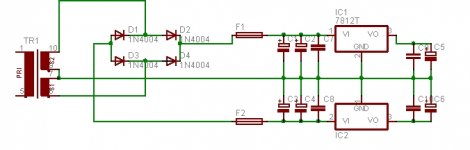
trafo is 2x12V and 2,25VA per secondary winding.
capacitors are 150uF-150uF-100nF before the regulator and 100nF-220uF after.
I tested the supply with a 4,7K and later a 1K load and it worked fine, then I connected it to the preamp and one of the regulators stopped working.
they are (+ - )12V and rated to 1,5A
capacitors are 150uF-150uF-100nF before the regulator and 100nF-220uF after.
I tested the supply with a 4,7K and later a 1K load and it worked fine, then I connected it to the preamp and one of the regulators stopped working.
they are (+ - )12V and rated to 1,5A
Attachments
Well, I had at bigger transformer earlier. 17,5V and 85mA per winding.
I went over to the local supermarket just now and bought a 9V battery. The Preamp works, thats for sure. I did however blow a pair of speakers earlier trying it with the powersupply. Cheap pieces of crap but the were useful when testing amps.
I went over to the local supermarket just now and bought a 9V battery. The Preamp works, thats for sure. I did however blow a pair of speakers earlier trying it with the powersupply. Cheap pieces of crap but the were useful when testing amps.
Hi again, I built a powersupply using the datasheet for the 7812-regulators and etched a new pair of Mono-yardbird PCBs. I have 47pF on the cap designated CRF and on the RG I have 0,85R since I didn't have the exact value.
My casing is made of MDF with aluminumfoil on the inside connected to ground. Internat wire is unshielded.
The problem is a buzz combined with a sparking sound that is more or less constant. What should I look after to solve this?
My casing is made of MDF with aluminumfoil on the inside connected to ground. Internat wire is unshielded.
The problem is a buzz combined with a sparking sound that is more or less constant. What should I look after to solve this?
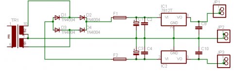
An update and some changes. I added 470uF between each fuse and the first capacitor.
So on the positive rail it's fuse->470uF->0,33uF->reg->0,1uF
and on the negative it's Fuse->470uF->2,2uF->reg->1,0uF
The positive, negative and common rail ends with a dual pinhead which connects to the two boards.
So the powerstarground is at the PSU-board and the signalground is as specified on the board. The signalground of each channel is separated from the common with a 0,82ohm resistor.
When the CD is connected to the poweramp directly there's no buzzing sound so it should be the pre that is the source.
Attaching a schematic of the PSU (one psu to two channels)
Attachments
No, Swedish apartmentbuildings doesn't have i mainsground in the wall-socket. It is stated in some law that when renovating a threepronged socket containing mainsearth must be installed but that is when and if thers a renovation. So no.
And I can't seem to think of a way to seperate the ground of the two channels.
Oh, one more thing. If I disconnect the ampboards from the PSU and drive one channel only with a 9V battery, when there's still buzzing.
And I can't seem to think of a way to seperate the ground of the two channels.
Oh, one more thing. If I disconnect the ampboards from the PSU and drive one channel only with a 9V battery, when there's still buzzing.
kmj said:Oh, one more thing. If I disconnect the ampboards from the PSU and drive one channel only with a 9V battery, when there's still buzzing.
You could not power it from a single 9Volt.
You would need two, connect in series, with the mid point (where you connect the two) being your ground.
Cheers!
Russ
kmj said:Ok, I just tested but Batterypower is not an option i'm sorry to say. It's for a friend not fond of the id�a.
And did it work?
If it did then the problem is with the PS.
Do you have a dual scondary trafo?
If so I would use two bridges.
kmj said:Oh, you missunderstood me. I just tested with the one battery. I only have one but I could buy another tomorrow. And I have more bridges to add if it might help. And the trafo has dual secondaries
It would make better use of the trafo.
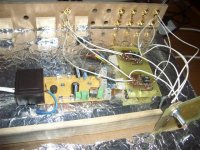
kmj said:I measured the voltage to approx 11,9V positive and negative. The layout is from the datasheet exept for the added 470uF caps, shouldn't it be good enough?
Attatched a pic of present setup, one channel disconnected.
Is it possible you have the opamps on the solder side?
If so they are upside down.
Not if you turn the paper upside-down when putting it in the UV-boxIs it possible you have the opamps on the solder side?

I managed to etch it on the wrong side and that's why the OPs are on the copperside, they are however correct. Forgot to mention it
")
I went for a run to the nearest gasstation and I'm now in possesion of two 9V batteries. Stay tuned!
- Status
- This old topic is closed. If you want to reopen this topic, contact a moderator using the "Report Post" button.
- Home
- Amplifiers
- Chip Amps
- The "Freebird" ultra clean ultra simple preamp design