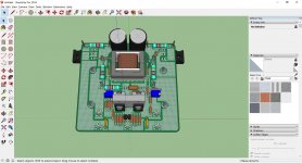
only 7.5mm lead space?
JP
Someone might have another brand of cap with smaller lead spacing.
Good to have both 5mm and 7.5mm lead spacing options.
Version with solder tags (visible posts at ends of power resistors) enabling if desired/needed paralling of degenerating resistors. Working in Z axis to reduce overall PCB dimensions and if stacked, better power distribution (mounting PCB parallel to main heatsink).
Collecting more comments to, one day (I hope soon), fix the design for prototype. For the moment I´m missing more interested diy´er.
Still waiting for PCB board level transformer shielding.
JP
Collecting more comments to, one day (I hope soon), fix the design for prototype. For the moment I´m missing more interested diy´er.
Still waiting for PCB board level transformer shielding.
JP
Version with solder tags (visible posts at ends of power resistors) enabling if desired/needed paralling of degenerating resistors. Working in Z axis to reduce overall PCB dimensions and if stacked, better power distribution (mounting PCB parallel to main heatsink).
Collecting more comments to, one day (I hope soon), fix the design for prototype. For the moment I´m missing more interested diy´er.
Still waiting for PCB board level transformer shielding.
JP
This version fixes all issues with the original pcb.
The only thing required to gain new interest would be to show Nelson using your pcb with 32V rails, and his new Cinemag transformer.
That would raise some eyebrows.
IXTH64N10L2 can easily dissipate 60W
Or just label your pcb F6 Nitrous.
Quite a few motor heads around here.

Last edited:
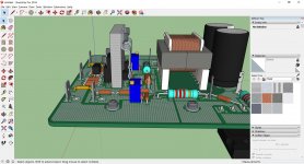
Transformer PCB board level shielding.
Board Level Shielding Configurable Sales Drawing PDF Download Page
JP
Board Level Shielding Configurable Sales Drawing PDF Download Page
JP
Simply M3 (#5) drilled piece of aluminium.
Retaining spring:
THFK 220, Retaining springs for transistors, Heatsinks f.cool, Fischer Elektronik
JP
Retaining spring:
THFK 220, Retaining springs for transistors, Heatsinks f.cool, Fischer Elektronik
JP
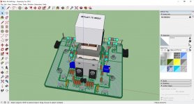
Bloody beautiful.
Erm Ok Remembering of course that's only a Sketchup image.
Most Anybody can make / concoct an image using Sketchup.
IF willing to spend the screen time on it.
Far.... more convincing to see a Photo.
I´m waiting for transformer board level shielding quotation (needs to be symbol defined and routed) before ordering PCB.
110x103x2mm, 70µm, HAL, green, white top silkscreen, batch of ten.
P.S.: all my board are 3D modelled before ordering for last check and believe me, the model is not far realistic from the produced boards.
JP
110x103x2mm, 70µm, HAL, green, white top silkscreen, batch of ten.
P.S.: all my board are 3D modelled before ordering for last check and believe me, the model is not far realistic from the produced boards.
JP
- Home
- Amplifiers
- Pass Labs
- The diyAudio Firstwatt F6