I went with 0.62 ohm and it sounds fine. CL6 suggested to me to use 0.56 wirewound and if I am correct that is what he used. I have since used resistor in parallel formula with my 0.62 to bring it down to 0.55 and I did not notice any difference in the sound to my ears. When I make a new order I will purchase a wire wound 0.56 ohm and may replace my 0.62 just because that is what NP describes.
Hi guys, I recently started building an F6 pretty much from scratch. I made my own PCBs and stuff rather than using the ones in the DIY store. I just have a couple questions before proceeding with placing the parts:
In the (incomplete) F6 build guide a 9.1V zener diode and 110Ohm resistors in place of the 47Ohm R11/R12 from the schematic. Would you recommend that i proceed with the values used in the guide or the schematic? Does it matter?
Also, when I first apply power does the pot need to be set to a certain position to avoid damage to components?
Considering I built the PCB myself I want to be very careful not to damage any components if there is a problem..
This is the first time I've built an amp like this so i am kinda new to this.. If you have any other recommendations I would really appreciate it.
Hi Forum,
I've been wondering for a few days about the following:
Is it possible to build an F6 using P-channel devices (e.g. IRF9240)? I understand that some rewiring must be necessary, but is it possible? And would there be any obvious drawbacks? Have anyone tried? Should I try?
I've been wondering for a few days about the following:
Is it possible to build an F6 using P-channel devices (e.g. IRF9240)? I understand that some rewiring must be necessary, but is it possible? And would there be any obvious drawbacks? Have anyone tried? Should I try?

Hi Forum,
I've been wondering for a few days about the following:
Is it possible to build an F6 using P-channel devices (e.g. IRF9240)? I understand that some rewiring must be necessary, but is it possible? And would there be any obvious drawbacks? Have anyone tried? Should I try?
Yes, just reverse the power supply polarities, the zener bias polarities, and the electrolytic cap polarities. Flip the input buffer supply connections so the top one still goes to the + supply.
Is it possible to build an F6 using P-channel devices (e.g. IRF9240)?
Yes, just reverse the power supply polarities, the zener bias polarities, and the electrolytic cap polarities.
Flip the input buffer supply connections so the 2SK170 still goes to the + supply.
but - why ?
Mostly because I am curious. I am soldering together my first F6 these days, and I realized the all the amplifiers I have seen that does not use a complementary pair uses n-channel (or npn in the good old days) transistors. And I started to wonder if there is a reason for this.
And the question remains - Why not?
Yes, just reverse the power supply polarities, the zener bias polarities, and the electrolytic cap polarities.
Flip the input buffer supply connections so the 2SK170 still goes to the + supply.
Thanks
")
I realized the all the amplifiers I have seen that does not use a complementary pair uses n-channel
(or npn in the good old days) transistors. And I started to wonder if there is a reason for this.
The P channels don't have as good electrical characteristics as the N, but you certainly can use them.
.....
And the question remains - Why not?
in this case - having already functional schematic with one polarity , it is trivial to make amplifier with opposite outputs polarity
in some other case , if using preputium class outputs , and obtaining opposite sex outputs is easier ... there is valid reason
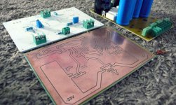
Here's a picture of the board I made..
Does anyone happen to understand why R11, 12 are 110ohm in the build guide while the original schematic uses 47ohm (I think he used a 9.1V zener instead of the 5.1V in schematic, as well?)
I've read through quite a bit of this thread and I can't seem to find an explanation so if there already is one I apologize, just please point me in the right direction. I am actually placing the components right now so I need to make a decision before I proceed.
Attachments
Here's a picture of the board I made..
Does anyone happen to understand why R11, 12 are 110ohm in the build guide while the original schematic uses 47ohm (I think he used a 9.1V zener instead of the 5.1V in schematic, as well?)
I've read through quite a bit of this thread and I can't seem to find an explanation so if there already is one I apologize, just please point me in the right direction. I am actually placing the components right now so I need to make a decision before I proceed.
The original F6 had those Semisouth power Jfets. Those did not require much voltage to get going. This diy version uses the good ol' IRFP240 mosfets which requires more oomph. Bigger gatestoppers just make for a better behaved amp, less likely to suffer parasitic oscillation.
Thanks for the response, however I am a little confused now. Is the schematic at the beginning of the thread
up to date and made for the IRFP240 or is there another?
It says mosfet, so it's for the IRFP240.
Here's a picture of the board I made..
Those look like nice, heavy-duty boards.
How did you make them?
Thanks...
- Home
- Amplifiers
- Pass Labs
- The diyAudio Firstwatt F6