If 12 includes the main PCB boards, which I understand it does, I'm good. Two main PCB boards and 10 small boards. All appear to be in good shape.M2x buyers: PLEASE open your package promptly and verify that you received all twelve PCBs in good condition. Undo the rubber bands and look in between for a little lagniappe.
Russellc
Edcor quoted me 8 week delivery and (I was lucky!) shipped in just 2 weeks. I called Mrs. Edcor (marketing dept) to say Thanks and she warned me, "Don't get used to it!".
Same thing when I ordered from them. I had them in hand in short order, way shorter than anticipated. This was back when M2 was still fairly new to the release list. Subsequent pieces came from Teabag sets.
Russellc
M2x buyers: PLEASE open your package promptly and verify that you received all twelve PCBs in good condition. Undo the rubber bands and look in between for a little lagniappe.
Whoops, I guess I am missing something? Looking at them I have the two main PCBs, 10 small mother boards, a pair of Toshiba K170/J74, a pair ofTucson, a pair of Norwood, a pair of N-Fet and emitter follower, a single Diamond dual follower (BJT), and a single Austin....guess I am missing 1 Austin board and one Diamond dual follower (BJT) ?
Wait a minute....I'm looking at two different sides, I think I have everything...closer look with old eyes, I have pairs of the following: Diamond dualfollower, Toshiba K170/J74, N-Fet follower, Norwood,and Tucson, so I guess I am good.
Russellc
Last edited:
Um, turn the boards over. Austin IS the Diamond dual follower. The Diamond dual follower IS Austin.Whoops, I guess I am missing something? Looking at them I have the two main PCBs, 10 small mother boards, a pair of Toshiba K170/J74, a pair ofTucson, a pair of Norwood, a pair of N-Fet and emitter follower, a single Diamond dual follower (BJT), and a single Austin....guess I am missing 1 Austin board and one Diamond dual follower (BJT) ?
Russellc
Ten is the correct number of daughter PCBs. 2xIshikawa , 2xAustin , 2xMtnView , 2xTucson , 2xNorwood.
I may have misunderstood, if you still think there's a problem please snap a photo?
M2x parts BOM questions
I guess this question would be for Mark and 6L6.
I'm putting together my parts list on Mouser and I've noticed possibly a typo on the BOM. R13 and R14 are listed as a value of 0R47, 0.47 ohms 3W and the part number given is 660-MOSX3CT631R4R7J. The mouser site shows this being a 4.7 ohm resistor. Just want to confirm which value it is, and if the schematic is correct.
Also, is there any reason that blade part number 571-624091 can't or shouldn't be used over part 571-638241-CT? The pcb pin width appears to be the same and it can be purchased individually as opposed to a roll of 100.
Also, the optional C1 cap on the Ishikawa input stage is not in stock at Mouser. Is there a recommended substitute for it?
Thanks!
Last edited:
Wow great catch! Indeed Nelson Pass's design does call for zero point four seven ohms as seen in post #1 of Nelson Pass's thread
Official M2 schematic
and indeed as shown on the M2x amp board V1b schematic. However the BOM is wrong as you point out! The correct part number at Mouser is
which I would be grateful if somebody double-checked that. I hope it is a 3 Watt, metal oxide resistor made by KOA Speer, resistance 0.47 ohms, size 6mm x 15.5mm. I will confer with 6L6 to see how we can update the BOM on the thread here.
As for parts substitutions (blades), feel free to make whatever changes you like. If it works, great. If it doesn't work, you can always go back and order the part# in the BOM.
Parts not in stock? Welcome to the reality of electronics. Now you get to learn how to use octopart.com. It's telling me that, today, DigiKey has 997 of those caps in stock, and Arrow has 994.
Official M2 schematic
and indeed as shown on the M2x amp board V1b schematic. However the BOM is wrong as you point out! The correct part number at Mouser is
660-MOSX3CT521RR47J
which I would be grateful if somebody double-checked that. I hope it is a 3 Watt, metal oxide resistor made by KOA Speer, resistance 0.47 ohms, size 6mm x 15.5mm. I will confer with 6L6 to see how we can update the BOM on the thread here.
As for parts substitutions (blades), feel free to make whatever changes you like. If it works, great. If it doesn't work, you can always go back and order the part# in the BOM.
Parts not in stock? Welcome to the reality of electronics. Now you get to learn how to use octopart.com. It's telling me that, today, DigiKey has 997 of those caps in stock, and Arrow has 994.
Last edited:
Wow great catch! Indeed Nelson Pass's design does call for zero point four seven ohms as seen in post #1 of Nelson Pass's thread
Official M2 schematic
and indeed as shown on the M2x amp board V1b schematic. However the BOM is wrong as you point out! The correct part number at Mouser is
660-MOSX3CT521RR47J
which I would be grateful if somebody double-checked that. I hope it is a 3 Watt, metal oxide resistor made by KOA Speer, resistance 0.47 ohms, size 6mm x 15.5mm. I will confer with 6L6 to see how we can update the BOM on the thread here.
As for parts substitutions (blades), feel free to make whatever changes you like. If it works, great. If it doesn't work, you can always go back and order the part# in the BOM.
Parts not in stock? Welcome to the reality of electronics. Now you get to learn how to use octopart.com. It's telling me that, today, DigiKey has 997 of those caps in stock, and Arrow has 994.
Hi Mark, this is what comes up on Mouser for the new part. Looks ok.
Attachments
As long as it obeys the BOM "15.5 x 6mm or smaller" size restrictions, a 4 watt resistor would be fine. I would avoid wirewound resistors in the source leg myself. Why don't you ask the actual amplifier circuit designer himself, Nelson Pass?
The small portion of M2x that I designed, uses dinky little semiconductors without heatsinks. Not the part with big He-Man MOSFETs bolted to heavy slabs of aluminum.
The small portion of M2x that I designed, uses dinky little semiconductors without heatsinks. Not the part with big He-Man MOSFETs bolted to heavy slabs of aluminum.
Um, turn the boards over. Austin IS the Diamond dual follower. The Diamond dual follower IS Austin.
Ten is the correct number of daughter PCBs. 2xIshikawa , 2xAustin , 2xMtnView , 2xTucson , 2xNorwood.
I may have misunderstood, if you still think there's a problem please snap a photo?
Wait a minute....I'm looking at two different sides, I think I have everything...closer look with old eyes, I have pairs of the following: Diamond dualfollower, Toshiba K170/J74, N-Fet follower, Norwood,and Tucson, so I guess I am good.
Russellc
ERROR IN M2X MAIN AMPLIFIER BOM HAS BEEN CORRECTED
Thanks to JSA1971's eagle eyes, a mistake in the Bill Of Materials for the main amplifier board has been found and fixed. You really do want R13 = R14 = 0.47 ohms, just as Nelson Pass's schematic calls for. Just as the M2x schematic calls for. Just as column C and column D of the BOM call for.
Unfortunately, I transposed three keystrokes of the Mouser Part# in the BOM, which accidentally and incorrectly pulls up a 4.7 ohm resistor. That's wrong! Just now I've fixed the BOM and good old 6L6 has made a ninja edit to post#1 of this thread, installing the correct BOM and vanishing the old wrong one.
Please discard all copies of the main amplifier BOM that you may have in softcopy form / on your hard disk / in your cloud storage. Please grab the latest and greatest from post #1.
I will see what I can do about the mirrored copy on Google Drive.
Many apologies for the error, and grateful thanks to those who found and fixed it!
Mark Johnson
Wait a minute....I'm looking at two different sides, I think I have everything...closer look with old eyes, I have pairs of the following: Diamond dualfollower, Toshiba K170/J74, N-Fet follower, Norwood,and Tucson, so I guess I am good.
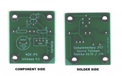
The side with lots and lots of geometric shapes in white ink ("silkscreen") is called the Component side.
The side without any white geometric shapes, is called the Solder side.
I recommend you turn all 10 daughtercards with the Solder side down and the Component side up. Now the names are visible and the descriptive slogans are invisible.
_
Attachments
Last edited:
The side with lots and lots of geometric shapes in white ink ("silkscreen") is called the Component side.
The side without any white geometric shapes, is called the Solder side.
I recommend you turn all 10 daughtercards with the Solder side down and the Component side up. Now the names are visible and the descriptive slogans are invisible.
_
yep, all's good, Tucson, Norwood, Ishikawa, Austin, Mt view...
Builders, please read post #3 before you begin your M2x assembly, it includes lots of useful little tips including this one:
Jumpers. When you look at the amplifier main board, you’ll see four white U-shaped markings inside the rectangle where the input stage module is bolted. Look for the text "I/O 1" , "I/O 2" , "I/O 3" , "I/O 4". The U-shaped markings are less than 1cm from those pieces of text. Just bend some scrap AWG22 wire into a U shape (resistor cut-off leads are perfectly fine too), stuff into the component side, add a piece of masking tape to hold it in place while soldering, and solder both ends on the back. Trim flush, remove tape, done. The purpose of these jumpers is to provide a safety backup, and a backup-to-the-backup, guaranteeing that the bolts are electrically connected to both sides of the amplifier main board. Even if the plated-through-holes somehow become no_longer_plated on this board. Yes we are preparing for a very unlikely tornado-during-earthquake event. But the cost of preparation is zero, so: why not?
- Home
- Amplifiers
- Pass Labs
- The diyAudio First Watt M2x