250 pieces MV5075C LEDs have arrived; selling at cost
Arrived today; photo below. Some M2X builders have already ordered and paid.
Arrived today; photo below. Some M2X builders have already ordered and paid.
I just ordered qty=250 pieces of the MV5075C LED from an authorized distributor and I'm confident these are not counterfeit. I paid USD 0.122 per piece, which is almost exactly 8 LEDs per USDollar.
These are used in the "Mountain View" input stage daughter card of the M2X amplifier.
I'd be glad to let other hobbyists have some of these at my cost, including my cost of postage and mailer envelope. If anyone wants to be a local re-distributor in parts of the world where Mouser doesn't sell the MV5075C (so far we know that Portugal and Finland are on this list), that would be a wonderful thing. Otherwise, small quantities only please. PM me with your needs and to get my PayPal info.
I estimate that shipping within the USA costs $4.50 and shipping outside the USA costs $14.50. Throw in the envelope and its 5 & 15.
Attachments
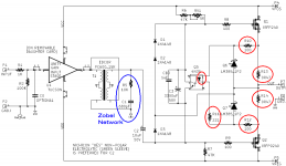
Thank you ZM! R13 and R14 must be gate resistors.
Made a mistake here by just assuming. R8 and R9 are gate resistors.
Edcor transformers for M2x: my order was shipped IMMEDIATELY
This morning I ordered eight of the Edcor PC600-15K transformers, for use in M2x amplifiers. To my surprise and delight, they emailed me back 90 minutes later (the same day! today!), to let me know that my order has been filled and shipped. Wow.
_

_
This morning I ordered eight of the Edcor PC600-15K transformers, for use in M2x amplifiers. To my surprise and delight, they emailed me back 90 minutes later (the same day! today!), to let me know that my order has been filled and shipped. Wow.
_
_
Attachments

First of all thanks to Mark for the transformer samples.
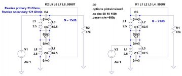
My attempts to measure model parameters have met with difficulty due to the large variation of primary inductance with signal level. I am using our Digilent Analog Discovery USB module in network analyzer mode and even down to 10mV the numbers change. I ended up using a rule of thumb (600 Ohm and -3dB point) to get close and then measured series resistance and inter-winding capacitance with a Beckman handheld impedance meter.
Surprisingly both 15dB and 21dB auto-transformer modes match sim vs measurement fairly well, with the biggest difference being less peaking at 20kHz or so. An appropriate R/C damping network could probably make both very flat at the top end.
The 21dB connection comes with a 4x increase in drive requirement but I also wanted to try something that came closer to a normal PA gain structure. The gain variation with level is mostly below 20Hz (this would obviously come with an increase in distortion vs level) and probably is borderline on audibility. I must say I have listened to and measured an inductor based equalizer where this behavior extends well into the audible frequency region and it is clearly a serious coloration (that some may like).
EDIT - For those that have not done this before the coupling factor K was empirical. The sensitivity to it is surprising at first, 1 is ideal but seemingly tiny deviations below this make big differences.
Attachments
Last edited:
the need for
hi fi equipment to take up large segments of living space.D
So do horses. Getting bitten by a daze that came from one of too many stables of my neighbors today reminded me.
(I have to cover up in some way that I'm reading Mr. Wurcer's posts)
Yes it makes you appreciate Nelson Pass's remark: "The purpose of building this equipment is entertainment. The customer's, and also my own." M2 seems to entertain many people very well, despite >200 ppm distortion (-74 dB). Oh the humanity.
What's worse, the variant with 8-legs blasphemy is just as entertaining as the one without, according to people who have tried both.
What's worse, the variant with 8-legs blasphemy is just as entertaining as the one without, according to people who have tried both.
From the Official M2 thread.
")
No problem Mark, I was actually curious about your view on not taking output of the AD744 from pin 5 which has some single ended negative phase K2 signature.If I ever decide to do that, it would probably be sometime after the diyAudio Store starts selling M2x boards. Certainly I'd wait until a few members have built and auditioned all five input stages on the Store PCBs, and shared their listening impressions & preferences. I'd probably post in the other thread, the one about M2x itself.
This is probably a stupid question, but I am going to shield myself behind 6L6's nice YouTube conference where he claims that 'the only stupid question is the one not asked'.
The BOM lists nicely most of the MOUSER part numbers, but the resistors are just 'named'. Put a 1K resistor. I know that for most of you, that is enough... but if you go here to an electronics store, you really get the lowest possible parts made in bulk with the lowest possible standards.
So, if I were to order resistors to stuff this incredibly tempting M2x (or any other PCB for that matter), what are the recommended:
- Power Ratings for those with un-listed power ratting? (I assumed 1W, but I could be so off I am asking nonetheless)
- Recommended type (or types)? There are options for Carboon Film, Ceramic Composition, Metal Film, Metal Oxide, Thick Film, Wirewound
- What is the recommended tolerance? Obviously the less, the better, but also more expensive. Is there a 'sweet spot' most folks prefer to rely upon? Or is this just a: "as low as you can afford it" type of scenario?
- Does voltage ratings matter or even apply?
- Finally, is there any 'preferred brand' that has proven to be more reliable or that just 'plays better' with this sort of amps?
Again, I know this is probably knowledge 101... so please be gentle!
Best regards,
Rafa.
Hi RafaPolit,
Im also new in the game and have no component preferences. I have used Vishay/Dale metal film and some Vishay / Beyschlag thin film in posisions where spesific components have not been recommended. I have several amps on hand for reference and my F6 and M2 sound great with those components.
There are general component guidelines in many of Nelsons First Watt articles.
Kjartan
Last edited:
In most cases Metal film, 1/2 watt resistors will be quite ok. If you read Mr. Pass articles you'll see that he usually specifies 1/4 watt metal film. Exotic or higher power resistors might offer some imaginable improvement but I'm sceptical.
Capacitors are a different story.
Hope this helps.
Cheers
Capacitors are a different story.
Hope this helps.
Cheers
I think what RafaPolit is trying to establish, is whether there is merit in importing audio-grade components, i.e. Vishay/Dale resistors - at great cost because he lives in a remote country (like myself) where the likes of Vishay/Dale are not found at the corner electronics shop, or even local mail order store.
In my case, I'm probably more fortunate to have a local RS Components which will import at reasonably fair cost.
In my case, I'm probably more fortunate to have a local RS Components which will import at reasonably fair cost.
Here in Thailand which you can buy exotic parts, people still buy whatever the local shops have and it still sounds great.
So buy whatever the local shops have with 1/4 or 1/2W should be fine.
If you can order from mouser or farnell just buy vishay mrs25, it's small foot print resistor with 0.6w, plenty for almost every projects.
So buy whatever the local shops have with 1/4 or 1/2W should be fine.
If you can order from mouser or farnell just buy vishay mrs25, it's small foot print resistor with 0.6w, plenty for almost every projects.
Start with R13-R14. They are 0R47 3W 5% metal oxide resistors and a specific part number is given in the BOM. You need four pieces of this resistor to build a stereo pair of M2(x) amplifier boards. However, what I actually do is purchase ten pieces of this resistor, and then use my DVM to find the four resistors that are closest to 0.470 ohms. The cost is modest: $2.10 for ten resistors.
The remaining resistors can be 250 mW (or higher), 5% tolerance (or better). I myself always buy 1% metal film resistors and if possible, 600 mW. About half of the resistor values I want, are available at Mouser in 600 mW metal film. Here is one example: Mouser Link: 603-MF0207FTE52-221R . When 1% at 600 mW is not available for a certain resistor value, I buy 1% at 250 mW metal film. Why do I use 600 mW resistors when 250 mW is adequate? It's extra margin of safety and the additional cost is low.
For those who might wish to boast that their M2 amplifier, lovingly hand-built in their own home workshop, is so much better than a standard M2, I offer the schematic below. Please observe that the negative feedback loop which sets Class A bias current, contains resistors R10-R14 and the LED side of Q5, marked in red. Why not use super tight tolerance components for those five resistors?? R13 and R14 must be hand selected: Mouser doesn't sell 3W 0R47 metal foil resistors at better than 5% tolerance. To get tight tolerance for R10-R12 you could buy 0.1% resistors from Mouser ($1.58 for the 0.1% 221R, $0.60 for the 0.1% 100R), or you could hand select parts on your recently calibrated, 4.5 digit DVM. Once you've got super tight tolerance components for R10-R15, you know with certainty that the Class A bias current in your personal, hand built M2, is extremely tightly controlled**. Woo Hoo!
Naturally you could do the same thing upon the Zobel Network which terminates the Edcor transformer secondary. Read the application notes on Edcor's website and on the Jensen Transformers website; the Zobel Network subtly tailors the transformer's frequency response, to give exactly the sound and tone that Nelson Pass intentionally chose when he sized R5 and C1 originally. That's what you want, exactly, is it not so?
**There might be a wee imperfection in this procedure, which someone may point out. We'll see.
_
Attachments
Last edited:
Naturally you could do the same thing upon the Zobel Network which terminates the Edcor transformer secondary. Read the application notes on Edcor's website and on the Jensen Transformers website; the Zobel Network subtly tailors the transformer's frequency response, to give exactly the sound and tone that Nelson Pass intentionally chose when he sized R5 and C1 originally. That's what you want, exactly, is it not so?
_
Don't you think that the variance in drive impedance might reflect enough to make the exact values different for each input stage? I don't know how much the transformers can vary.
As much fun as it is to build something with measured matching down to one femto-unit, reality says these amps will work with a wide variation of parts and values. Use what you can source, measure the parts you have and use the best in the critical areas, and the circuit will work and sound great.
Some of the various driver boards are going to be a little less tolerant of parts variation, but I'd suggest getting what you can and trying, this is a robust circuit.
Also - if you look at the part's listing on Mouser (enter the part number in the BOM and look at the page) all the data necessary to choose an equivalent will be there, as it will list value, tolerance, voltage rating, lead spacing and size, etc...
When "exactly" is desired, the Fairchild output Mosfets would be a better choice, like the original.... to give exactly the sound and tone that Nelson Pass intentionally chose when he sized R5 and C1 originally. That's what you want, exactly, is it not so? ...
- Home
- Amplifiers
- Pass Labs
- The diyAudio First Watt M2x