@jwilhelm
Speaking for myself I would never do it the way you did but tap the different circuits from a common point after the humbuster.
As I see it your problem is imagining you can have two independent "star grounds", both lifted from the chassis common, powered from shared transformer secondaries. I haven't done it, but it just seems counter-intuitive to me to expect it would work.
Attachments
It works perfectly as I had it drawn. It allows two amplifier channels to operate with no ground loop hassles or cross-talk between supplies, yet operate from a single transformer. Both amplifier channels operate very quietly and with an excellent soundstage. The troubles begin if the transformer wiring is altered.
The amp has been built many times with connections as my diagram shows with no issues whatsoever and output measurements surpassed what the designer expected. Sons of VHex I put a lot of work into separating each channels grounds though-out the whole amplifier including protection circuits. Using one common ground for both supplies would really be a waste as it would be susceptible to ground loops. My point was in this type of application you can't just connect the transformer any which way without consequences. It needs to be wired symmetrically in this application.
It worked because you didn't need actually dual mono supplies - all that extra hardware isn't gaining you anything over the regular shared supply as I drew it above. If you are lucky, it won't mess things up. If you are not lucky ...
And to reiterate, there is no way to wire the configuration you show any other way than "symmetrically" because there is no distinction between the rectifier AC terminal connected to what you call "0 V" and the one you labelled "High Volt".
And to reiterate, there is no way to wire the configuration you show any other way than "symmetrically" because there is no distinction between the rectifier AC terminal connected to what you call "0 V" and the one you labelled "High Volt".
Last edited:
Dual mono supplies make a huge improvement in the soundstage of this amplifier.
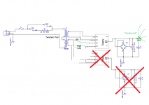
With the output windings of the transformer connected in series, the center tap would be 0V and the other two windings will have a voltage potential that is positive and negative of zero. This was added to the diagram to help the builder figure out where to connect each wire from the transformer.
With the output windings of the transformer connected in series, the center tap would be 0V and the other two windings will have a voltage potential that is positive and negative of zero. This was added to the diagram to help the builder figure out where to connect each wire from the transformer.
Maybe I'm missing something but I don't see why the charging current from supply 1 would return through supply 2. The ground lift resistors in the amplifiers would add 20R resistance between them through the input interconnects. Current would take the easiest path back to it's own supply.
D16 is on a circuit that is isolated from D1.Charging current through interconnect and amp ground.
D1 - C1 - amp gnd - amp1 gnd - D16
The current cannot return to winding 1/2 via winding 3/4.
I'm not sure what else you hope to see on the schematic. It has the mains connection, transformer, supplies, loop breakers, amps, source and speaker connections. If you see a legitimate issue with this wiring scheme I'd like to hear it, but if not I've heard enough. Two very respected members here have worked closely with me in this design and neither see an issue with it. It works perfectly as intended. As I said before, I'm just pointing out in this particular design you do need to be careful how the transformer connections are made as it can cause issues with grounding.
Some discussion on the practical current carrying capability of small diodes is presented in:
dalmura.com.au/static/Power%20supply%20issues%20for%20tube%20amps.pdf
dalmura.com.au/static/Power%20supply%20issues%20for%20tube%20amps.pdf
Jwilhelm, your schematic is basically the same as the one posted by ctrix. D2 is parallel to D12 and that the loop breakers don't separate the power or input grounds. How do you think that the circuit works?
Normally I would post better information. This week I am stuck with communicating through my phone.
Normally I would post better information. This week I am stuck with communicating through my phone.
Last edited:
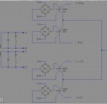
My schematic is not the same as the schematic shown by ctrlx. The schematic he showed has the supply grounds directly connected to each other, so there is no way to control which diode will complete each circuit, so current will likely flow through the diode with the lowest forward voltage.
My schematic shows the supply grounds connected to each other through a loop breaker. The supplies are connected to their respective amplifier channel independently. The only connection between each amplifier is through the audio input ground which as in any properly designed amplifier also has a lifted ground/loop breaker incorporated into it as well. This lifted input ground gives a 20R resistance between both input channels. In my schematic there is no location where both supply grounds are directly connected to each other so the opportunity for current to return through the wrong supply diode is very unlikely unless there is a serious difference in diode forward voltage or a damaged diode. Measured voltage discrepancy between supply grounds in my own builds has been in the low uV range with amps idle or loaded. Hum is inaudible in all my builds. Noise on outputs is 80uV.
Early in the design stage of this amplifier I noticed the sound stage was good, but not excellent when two channels of these amplifiers were sharing a common power supply. They are very immune to RF and external influence, and also have very good PSSR, but as with just about any amplifier design, sound stage could be improved with monoblock configuration. The intended design of the amplifier was to be a compact design budget build that is easy to build and power up successfully for new builders. Due to cost and size constraints we opted for a shared main power transformer. We arrived at the supply design in the schematic as the best option to maintain channel separation for both power and audio and it has worked well in very many builds to date all over the world. Mostly this has been built by fairly new builders and we've given a lot of support through our website email and have heard from just about every builder, so if there was an issue with any of the builds we would likely have heard about it by now. As far as I'm aware everyone has been very happy with these amplifiers.
- Status
- This old topic is closed. If you want to reopen this topic, contact a moderator using the "Report Post" button.
- Home
- Amplifiers
- Power Supplies
- The DBRB | dual bridge rectifier board