Converting the schematics into pdf has no meaning because you would not be able to run to get the frequency response.
With 6 circuits in the same file, you won't see much even if I plot it out for you.
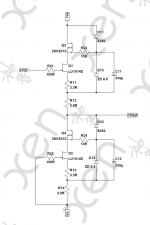
I think the best is to sort out your LT Spice so that you can read the asc file.
It contains no special components, just passives and a couple of LT1010s.
Patrick
With 6 circuits in the same file, you won't see much even if I plot it out for you.
I think the best is to sort out your LT Spice so that you can read the asc file.
It contains no special components, just passives and a couple of LT1010s.
Patrick
Referring to the article by Dimitri Danyuk :
http://www.angelfire.com/az3/dimitri/images/ew0805.pdf
When compared to other cross feed circuits, the Danyuk cross feed has the advantage that :
1) it has no built-in treble boost;
2) the cross feed frequency and amount are individually adjustable by separate stereo pots.
But it requires an extra buffer after the LP filter.
So I was thinking whether it can be done completely passively, if I am willing to sacrifice some independence in the adjustment.
The result is shown here (I hope Dimitri would not mind).
In this reduced passive form, it has a lot of similarity to the Linkwitz / CMoy crossfeed schematics.
By adjusting a few values, one can adapt the CMoy to a randomly chosen level of cross feed frequency and amount in the Danyuk.
So one can use the same PCB to cover both, if so wished.")
Patrick
.
http://www.angelfire.com/az3/dimitri/images/ew0805.pdf
When compared to other cross feed circuits, the Danyuk cross feed has the advantage that :
1) it has no built-in treble boost;
2) the cross feed frequency and amount are individually adjustable by separate stereo pots.
But it requires an extra buffer after the LP filter.
So I was thinking whether it can be done completely passively, if I am willing to sacrifice some independence in the adjustment.
The result is shown here (I hope Dimitri would not mind).
In this reduced passive form, it has a lot of similarity to the Linkwitz / CMoy crossfeed schematics.
By adjusting a few values, one can adapt the CMoy to a randomly chosen level of cross feed frequency and amount in the Danyuk.
So one can use the same PCB to cover both, if so wished.
Patrick
.
Attachments
While waiting for the Beta tester to build (he already has all the parts from us), I thought I would make an update.
Quite some time ago, we were challenged to make a High Power DAO to drive the Hifiman HE6 :
http://www.diyaudio.com/forums/head...lass-zgf-headphone-amplifier.html#post3293956
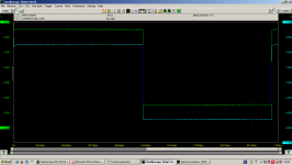
Well, we took on the challenge, and I tested the DAO HP today.
It has 2SK1529 cascode, +/-35V rails and 330mA bias.
Works first time. Almost boring.
It is unstable without load, so I used a somewhat heavy handed Zobel at 600kHz.
It is still -2dB at 1MHz as is, and hardly changes with a 27R load.
I could have use less Zobel to get even higher bandwidth.
But with so much power on hand, I think I'll leave it as is .....
Patrick
PS Green is input, Cyan is output.
.
Quite some time ago, we were challenged to make a High Power DAO to drive the Hifiman HE6 :
http://www.diyaudio.com/forums/head...lass-zgf-headphone-amplifier.html#post3293956
Well, we took on the challenge, and I tested the DAO HP today.
It has 2SK1529 cascode, +/-35V rails and 330mA bias.
Works first time. Almost boring.
It is unstable without load, so I used a somewhat heavy handed Zobel at 600kHz.
It is still -2dB at 1MHz as is, and hardly changes with a 27R load.
I could have use less Zobel to get even higher bandwidth.
But with so much power on hand, I think I'll leave it as is .....
Patrick
PS Green is input, Cyan is output.
.
Attachments
Is there any alternative N-Channel misfit that will work in this circuit? Obviously 2SK2013 is getting hard to find these days, especially matched or in the quantity needed to get a good match.
Would FQP3N30 work? Or even IRF610 or 510?
Would FQP3N30 work? Or even IRF610 or 510?
Attachments
I have not tested others, so cannot guarantee the same triode cell characteristics.
But if you were to try FQP3N30, you need to change the Zener to 9V1.
And you might need other Zobel values for stability without load.
The exact value you need to test (with a sweep sine func gen and a spectrum analyser).
Patrick
But if you were to try FQP3N30, you need to change the Zener to 9V1.
And you might need other Zobel values for stability without load.
The exact value you need to test (with a sweep sine func gen and a spectrum analyser).
Patrick
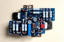
I wish to refer to post #205 and point out a small change which is at least necessary for any public build.
My apologies for not mentioning earlier.
If you look at the photo carefully, the TCS daughter board has been changed to TCSV3B.
B stands for bipolar transistor (unfortunately).
The reason for the change is that in the schematics shown in P.3 of :
http://www.diyaudio.com/forums/head...ss-zgf-headphone-amplifier-2.html#post3297425
the 2SJ74 ued for Q5 will see more than 40V.
This is above the rated Vds for the JFET.
One solution is to cascode it with a 2SJ103, but even that gets marginal for the standard DAO.
For the DAO HP it is still no go.
Hence the need to change Q5 to 2SA970BL, also for the standard version.
This will be revised once the Beta Tester has finished his build.
Patrick
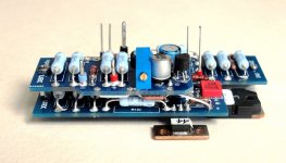
If you are referring to post #194 then the PCBs are done and soldered, but I have not yet have time to fiddle with the mechanics.
A test is planned with the 2nd Beta tester for the F5-HA to compare this against a standard ALPS.
But he is not yet far enough with his soldering. Will take a couple more months I guess.
On the DAO Beta test, the PCBs are soldered, ready for test.
But people with family are all busy before Xmas.
So probably won't be ready to post before January.
All in progress, just take time.
Patrick
I'm in no hurry, just wondering about it before all goes quiet...
Nothing about the DAO beta build will go quiet.
As said above amplifier boards are soldered, so that leaves the psu part.
A fat custom made transformer is sitting on my desk since yesterday, so slowly things are coming together!
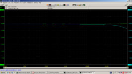
And for those interested in the high power version for the HE-6, here is a plot of the 500mA triode cell.
Patrick
.
Hi Patrick,
I'm studying a version of this follower for an 8 to 25 ohm, 110 dB/W compression driver, and plan to compare it to a DAO using the ZV9 triode cell. Do you recall the values used to make the 500 mA cell described in Part 2b? You mentioned experimentation and simulation brought you to some values, I'm hoping to use those as a staring point.
Thanks
Adam
Nothing about the DAO beta build will go quiet.
As said above amplifier boards are soldered, so that leaves the psu part.
A fat custom made transformer is sitting on my desk since yesterday, so slowly things are coming together!
Can hardly wait to see your implementation of it....judging from your others....i am expecting something really nice.
- Home
- Amplifiers
- Headphone Systems
- The DAO SE all-FET Class-A ZGF Headphone Amplifier