You're welcome!
??? What horn are you referring to?
Regardless, the goal is to design to a specific polar response over 'x' BW with it being big enough to properly load it at 'y' XO point/slope at 'z' rated power, so a bit of a juggling act for just a basic horn, so breaking it up into individual cells can require some differing contours as one moves off axis, which in turn might require rethinking the basic horn design if you can't get the desired horn design to fit over whatever arc is desired.
Then again, as simple as the pioneer's horn designs are, I've ~assumed they designed them first based more on construction/assembly, which in turn only required a 'one size fits all' driver for a given throat size.
IOW, if you use a W.E./Lansing/Altec design CD, then you can just copy existing horns close enough just fiddling with Hornresp's designer or once done, use its scaler program for different size throats, cutoffs, etc. and guessing why there's recently been a plethora of new metal, wood horn boutique shops popping up on FB, webzines and other places.
Last edited:
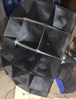
gac800, the spacers in the front are given by the construction - see the pictures in the begining of the thread. Typically, you glue 3 cells together on the edges. When you put two triplets together so that the corners on the edges touch, you get this shape of space in between. The front of the horn approximates a part of a spherical surface. If one had great 3D designing skills, the cells could be made in a way that they touch each other on the edges. I saw somewhere (maybe this thread) an article on how to make a 2x4 horn from tinned sheet metal - and the cell walls were made in a way that the mouths were trapezoidal and could be directly soldered together on both ends with no gaps. For the wooden construction (and my simple 3D printed version), bulding square cells is easier.
What about the spacing between the cells, it looks to be about an 1” in the middle row and then just tapered to a triangle on the top and bottom rows. Is there any specific math for this or is it just aesthetic?
I asked the same question, or a very similar at least, earlier in this thread. After having thought about it thoroughly, the reason became clear: You basically can glue together a almost infinite row of cells two dimensionally without getting gaps. But if you're going into the 3rd dimension, those rows get into contact just in the uppermost and lowermost corners, leaving space everywhere else.
Anyway, I don't have algorithms to compute the wedges either.
Best regards!
Hi pelanj
beautiful build.
for the throat shape see this cNC build thread (french) for the renowned and rare Onken 200 Wood : actually the cells start are cut to be in an horizontal plane, there is a pix https://forums.melaudia.net/showthread.php?tid=8255&page=3
best
Jean-Louis
beautiful build.
for the throat shape see this cNC build thread (french) for the renowned and rare Onken 200 Wood : actually the cells start are cut to be in an horizontal plane, there is a pix https://forums.melaudia.net/showthread.php?tid=8255&page=3
best
Jean-Louis
Hi Pelanj
the first pictures have gone, I think they were hosted externally, but afterwards it works. the 3D drawing is also available.
the MS200 wood has slightly less coverage than Altec 1505 which is better in home environment with (often) more early reflection. It is used by Akihiro Kaneda by example.
the first pictures have gone, I think they were hosted externally, but afterwards it works. the 3D drawing is also available.
the MS200 wood has slightly less coverage than Altec 1505 which is better in home environment with (often) more early reflection. It is used by Akihiro Kaneda by example.
I had forgotten, my bad, the author started another thread with all pix here. Still in french but Google will help you well https://forums.melaudia.net/showthread.php?tid=10115Hi Pelanj
the first pictures have gone, I think they were hosted externally, but afterwards it works. the 3D drawing is also available.
the MS200 wood has slightly less coverage than Altec 1505 which is better in home environment with (often) more early reflection. It is used by Akihiro Kaneda by example.
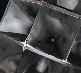
Something interesting, the walls of the cells are doubled and sanded in between.
best
Jean-Louis
Last edited:
I went through that thread and even found my pictures") I thought my project was crazy, but it is nothing compared to that gentleman's project. 4 kg of material and 30 hours of print per cell and 120 kg total weight finished. Wow. I need to try his method of sand filling on some smaller project.
I thought my project was crazy, but it is nothing compared to that gentleman's project. 4 kg of material and 30 hours of print per cell and 120 kg total weight finished. Wow. I need to try his method of sand filling on some smaller project.
I thought my project was crazy, but it is nothing compared to that gentleman's project. 4 kg of material and 30 hours of print per cell and 120 kg total weight finished. Wow. I need to try his method of sand filling on some smaller project.Jean-Luis, there should be a 3D model of the Altec multicell horn at this page - but I see only attachment number - is that also lost? https://forums.melaudia.net/showthread.php?tid=7081&page=24
So after my first listening experience with multicell horns, I must say that even though it is old technology, they can work pretty good. However I do not think this would be exclusive to multicell horns - IMHO any large non-beaming horn (playing 450 Hz to 4500 Hz) would "sound" very similar. E.g. my JBL 2380 clones are too small compared to these and the XO point had to be higher (above 600 Hz). And that made a difference. Even then, the 2380s were not too bad, but the large horn is better.
A funny thing is - when I was setting up the HF horn, it did seem too soft. Like playing almost nothing. Turning it off showed that even this "nothing" is very important - and the sound just locked in place.
I think it must be the non-beaming thing that creates this "speaker disappearing" effect across a quite large area (two or maybe even 3 seats)
So my conclusion from this project is, if I can get the telephone band covered with a single source with good dispersion, I will be happy. A DSP processed Unity horn should be able to do this and more.
You don't need DSP, even though mine have been active since I had them. William's passive version sounded excellent when I hard them a decade or so ago.A DSP processed Unity horn should be able to do this and more.
Sure, which is why I did it. Plus the passive was gonna cost a couple of hundred $ and I had the DSPs and amps so I just had to solder up some cables.Yes, I do not need a DSP, but it is so much easier with one.
bless up tractrixfreak,Spredsheet
Hello there in hornland,
- I was impressed, when I stepped into this tread. With the help of a friendly forum member I got the spreadsheet and I am happy to resend it to other enthusiasts. It would be fine to see here some photos of people who did make copies....
Cheers, Hajo
would love to have a copy of the spreadsheet for the plans. Thank you in advance!

I was too optimistic. There are some cracks from the foam hardening. Also, the filling is a bit uneven, I can still feel some voids behind the walls. On the other hand, where there was the correct amount of foam, it feels really solid and damped.
Maybe one could prevent the cracks if doing it in steps or even during build up (filling the triplets first and then after gluing two triplets together), but I cannot recommend the PU foam for this purpose. Maybe casting (non expanding) polyurethane would be better.
I think the horn would be still repairable, the cracks could be filled and there would be no measurable influence on sound, it would just not look as good.
Anyway, this was a very enjoyable project and it served as a proof to myself that multicell horns can work really well.
Attachments
- Home
- Loudspeakers
- Multi-Way
- The construction of a multicell horn