Xformer
DT -
Yes, I gathered that from your posts. Since I purchased it, I'll use the fancy ApexJr wire.
It won't result in any measurable difference, but as this is the diyaudio forum, I'll claim a vastly improved visceral experience with all audio equipment using a power supply tested with my clone compared to yours
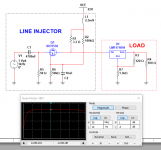
So my first conclusion is that for tube preamp power supplies, the Jensen JT-123-BLCF transformer is going to be adequate for measuring PSRR, output impedance, and stability using the non-invasive (phase margin) method described in: https://www.omicron-lab.com/fileadm...ote_TraditionalNoninvasive_Stability_V1_3.pdf
This Jensen JT-123-BTLCF transformer was shown in an AudioPrecision application note Technote 106: Measuring PSRR (Power Supply Rejection Ratio) - Audio Precision The article a useful current of 500mA after which the transformer distorts.
You'll have to register with AP to enable downloading.
This Jensen JT-123-BTLCF transformer was shown in an AudioPrecision application note Technote 106: Measuring PSRR (Power Supply Rejection Ratio) - Audio Precision The article a useful current of 500mA after which the transformer distorts.
You'll have to register with AP to enable downloading.
Hello Jack,
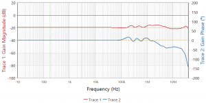
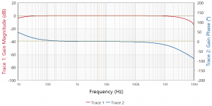
I like the look of what you are speaking about. I do have a couple of questions. How did you have the Jensen transformer set up for the plot you posted above? Posted below is a plot of the JT 123 BLCF tested with the primary coils in series and the secondary coils also in series terminated with a 10R dale metal film resistor.
What voltages are thinking the JT 123 BLCF is safe to use in the Vacuum tube world? The temporary breakdown voltage test voltage listed in the Jensen data sheet is 250 between windings and 500 to ground.
Thanks DT
Attachments
Last edited:
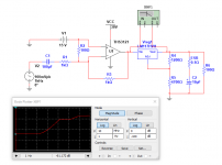
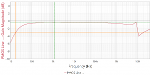
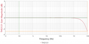
Can be normalized with the Bode-100 calibration regimen. Here's some actual results with the THS3121 (using a 1,000uF Nichicon). It's down 2.4dB@10MHz. I modified the evaluation module with a little help from the Dremel tool.
Attachments
Last edited:
Smoke On The Water
Hello,
Mostly staying indoors with the HEPA filter. California and Oregon are on fire. Look at this NOAA HRRR model of the smoke going past New Jersey.
Loop
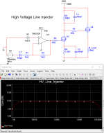
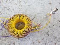
Take a look at this VAC 250F core with most of 100 turns of primary and secondary coils made of solid strand silver plated 20 AWG wire with 600V insulation.
The idea here is a core that is less permeability than the B-Wit 100 core to allow much larger asymmetrical current, several 10’s of ma without saturation is the plan. Not yet tested.
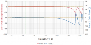
Low frequency response appears to be okay. HF looks possibly usable to 3 or 4 megs.
See the attached frequency and phase plot plus photo.
Thanks DT
Hello,
Mostly staying indoors with the HEPA filter. California and Oregon are on fire. Look at this NOAA HRRR model of the smoke going past New Jersey.
Loop
Take a look at this VAC 250F core with most of 100 turns of primary and secondary coils made of solid strand silver plated 20 AWG wire with 600V insulation.
The idea here is a core that is less permeability than the B-Wit 100 core to allow much larger asymmetrical current, several 10’s of ma without saturation is the plan. Not yet tested.
Low frequency response appears to be okay. HF looks possibly usable to 3 or 4 megs.
See the attached frequency and phase plot plus photo.
Thanks DT
Attachments
Hello,
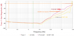
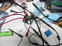
This is looking for the Sweet Spot. Most of these injection transformers are set up for only a few ma of current before they saturate.
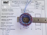
This transformer is wound on a VAC 250F core. This core has permeability that is much reduced from the VAC 500F core used in the B-WIT-100 transformer and will tolerate much more current before the onset of saturation.
The tradeoff is reduced band width, mostly trimmed off the LF end of the scale.
My impression is if you want to focus in on the LF use a different transformer. If you want to put the secondary of this transformer in series with the power supply to your audio amplifier to test PSRR this just might be the transformer to use.
This transformer is wound on a VACUUMSCHMELZE T60006-L2040-W964-02 250F core. There are 40 turns of CAT 6 plenum solid twisted pair.
DT
This is looking for the Sweet Spot. Most of these injection transformers are set up for only a few ma of current before they saturate.
This transformer is wound on a VAC 250F core. This core has permeability that is much reduced from the VAC 500F core used in the B-WIT-100 transformer and will tolerate much more current before the onset of saturation.
The tradeoff is reduced band width, mostly trimmed off the LF end of the scale.
My impression is if you want to focus in on the LF use a different transformer. If you want to put the secondary of this transformer in series with the power supply to your audio amplifier to test PSRR this just might be the transformer to use.
This transformer is wound on a VACUUMSCHMELZE T60006-L2040-W964-02 250F core. There are 40 turns of CAT 6 plenum solid twisted pair.
DT
Attachments
- Status
- This old topic is closed. If you want to reopen this topic, contact a moderator using the "Report Post" button.
- Home
- Design & Build
- Equipment & Tools
- The Bode-100 thread