Hello, I can't open this ASC with Altium Designer or PADS 9.5. What is the problem? What software is used to open?
As egra says, it is LTspice. Click my signature line to see how to get started.
After I’ve read Dermot Herrons great article about Blomley's amplifier I’ve decided to build this awesome amplifier. I designed my own PCB, and used quality parts. All semiconductors were closely matched.
Pros:
- Hyperdetailed sound (unexpected).
- Totally neutral. No warm (despite singleton input), nor sterile or dry .
- Dynamically and rhythmically strong
- Instrument separation
- Thermally and electrically stable
- Runs very cold
- Efficiency (~70%)
- Easy to build
Cons:
- A little bit weak in bass
- Need a sensitive speaker
- Build a high quality power supply for optimal result
This amp runs stable and sounds excellent. The Blomley Presence NS Class b amp is one of the very few solid state amplifier which totally free from transistor sound (grainnes).
Is it as good as a good Class A amp? Well, different. Blomley has fast, precise and neutral sound, and has much more detail than some Class A amp (compared to Hiraga 8W, JLH 1969). Extremely clean and and trasparent. I like it more, than Class A amps.
Dear sir, can you send me this pcb file? I like this amplifier very much and want to DIY it myself. Thank you!
As egra says, it is LTspice. Click my signature line to see how to get started.
Thank you sir, I use LTspice to open the analog diagram, and I need the PCB diagram.
Dear sir, can you send me this pcb file? I like this amplifier very much and want to DIY it myself. Thank you!
Some notes on construction. All small signal transistors are ztx453 / 553, except drives, they are Toshiba TTC / TTA 004B. If you want to use different transistors, check the pinouts. In the feedback network, increase the elko from 200uF to 470uF for proper bass response.
Attachments
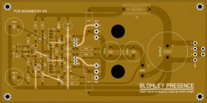
After I’ve read Dermot Herrons great article about Blomley's amplifier I’ve decided to build this awesome amplifier. I designed my own PCB, and used quality parts. All semiconductors were closely matched.
Pros:
- Hyperdetailed sound (unexpected).
- Totally neutral. No warm (despite singleton input), nor sterile or dry .
- Dynamically and rhythmically strong
- Instrument separation
- Thermally and electrically stable
- Runs very cold
- Efficiency (~70%)
- Easy to build
Cons:
- A little bit weak in bass
- Need a sensitive speaker
- Build a high quality power supply for optimal result
This amp runs stable and sounds excellent. The Blomley Presence NS Class b amp is one of the very few solid state amplifier which totally free from transistor sound (grainnes).
Is it as good as a good Class A amp? Well, different. Blomley has fast, precise and neutral sound, and has much more detail than some Class A amp (compared to Hiraga 8W, JLH 1969). Extremely clean and and trasparent. I like it more, than Class A amps.
Thank you very much sir,Do you stick to the original Blomley design?
Click to:
My 40-Year Love Affair with a Remarkable Amplifier—A Class B Amplifier for Audiophiles - Technical Articles
And yet Peter Blomley and his amplifier have gone virtually unrecognized in the audio world for more than 40 years. I suggest two reasons for this. First, his design was so original and so unexpected that few people understood it or took it seriously. Second, Blomley never put his design into commercial production because Plessey held the patent, so even fewer people were able to listen to it or review its performance.
Most of the audio hobbyists who constructed their own Blomley amplifier modified the design and in doing so introduced distortions. I suggest you build the original design (with perhaps just the minor modifications afforded by modern components) and listen to it. This will give you a reference sound to check any further modifications with which you might like to experiment.
The only component that is difficult to substitute is the OA47 gold-bonded germanium diode (GBGD). Some GBGDs are too high forward voltage and result in uncontrollable idle-current. I specified a Schottky diode but I don't think it works. well. Can't source OA47 or other GBGDs so far. Any suggestions?
Some notes on construction. All small signal transistors are ztx453 / 553, except drives, they are Toshiba TTC / TTA 004B. If you want to use different transistors, check the pinouts. In the feedback network, increase the elko from 200uF to 470uF for proper bass response.
Hello, sir. How to debug? What is the quiescent current? What are the input and output voltages? How are differential transistors paired? Thanks for answering
The original amplifier was specified for 15 ohm speakers. using 8 ohms causes problems because the higher current drive needed biases the -I presume protection - diode (D3) on before full output is reached.
As Trev said I had already put a Vbe multiplier in simply because of the scarcity of ge diodes. Though a Schottky might be an adequate replacement.
Some pointers for 8 ohms - reduce the emitter resistors in the power transistor stage (0.33 ohms) reduce the local feedback resistors R10, R6 to 100 ohms and 10 k respectively, reduce the current source resistor R9 to 4.7k to keep the balance, and the feedback resistor to 2.2k (halving the gain). I removed the diode D3 in the simulations as the local feedback voltage is now higher.
Also reduced the compensation capacitors C6 to 470pF and increased C5 to 68pF to keep the frequency response.
Overall distortion at 20kHz lower than simulated for original at 15 ohms. (.07%). Simulated THD at 1kHz in the region of .005%.
Not carried out any stability analysis. Expect it may need further optimisation as square wave shows ringing on negative edge, and less on positive edge but so did original, where the negative ringing may have been clipped due to the low bias on tr4.
It's tempting to separate the bias chain to Tr4/Tr5 from the collector load of Tr2.
The original article mentions 20mA. But the design is such that this should not matter as the output stage never cuts off. In theory.
Simulations suggest that at the high audio frequency of 20kHz the output devices remain on for longer and gradually reduce. I recommend 60mA where the minimum current does not fall below 20mA.
If you incorporate a Vbe multiplier instead of the Si+Ge diode then the setup procedure would be (I suggest):
Set bias pots to the diode end and vbe multiplier to minimum voltage.
Adjust Iq as per article using top bias pot to 20-60mA( your choice)
Adjust lower bias pot until current just increases
Adjust vbe multiplier until current just increases again.
Note that distortion at 20kHz (as simulated) is largely 3rd and other odd harmonics, indicative of crossover distortion. In this case it is more related to the phase splitter rather than output stage. Might not be audible, but may cause IMD products which are.
Lower distortion is possible when the Vbe multiplier minimises crossover distortion in the phase splitter.
Last edited:
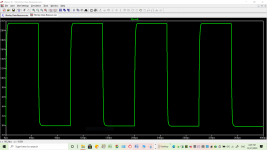
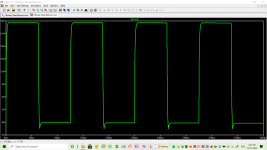
I have simulated this circuit on 10kHz square wave adapting Ian Hegglun's .asc file. The attached images and .asc file refer.
The problem was the value of R6 limiting the current flowing between the output and Q3 emitter. I reduced the value from 22k to 12k.
This had no significant effect to the output voltage however the output transistor standing current did increase to 136 m.A. putting this in the Class AB league.
I used 1N914 diodes for biasing since germanium transistors like OA47 are hard to find.
Attachments
I would be cautious about using two silicon diodes to bias the current splitter. They form a bias voltage for two transistors (possibly a BC546/BC556 now) and if not careful this may cause an excessive bias current. There is nothing to limit the current in these splitter transistors - and thermally, that is as bad as any bias compensation without mounting all on the same heatsink and even then needing power dissipation to be held similar (although for low power stages that may be less of a problem). I'd recommend using a Vbe multiplier as mentioned in my previous post.
I also noted the need to reduce the local feedback resistor but when investigating the option for making an 8 ohm load version of the circuit.
This design was such that the quiescent current in the output stage is never to switch off, so it largely should not matter what the actual quiescent current is. Except that higher currents which push the output transistors into a lower gain regime would increase the distortion rather than reduce it, perhaps, if older style transistors are used. i'm not sure what the classification of the original design would be. Class B possibly, except the output devices are not supposed to turn off, so not quite Class B so could never achieve the theoretical efficiency of a Class B (in theory).
If however the bias current from the phase splitter controls the output stage, as I think the use of two silicon diodes would, then I agree it has moved into Class AB.
I suggested a method of setting the bias using the Vbe multiplier in my earlier post.
Simulations indicate that distortion at 1kHz is low (.005% or thereabouts) but at 20kHz it is much higher and that the distortion components are odd harmonics indicating crossover distortion. What Blomley did was to move the crossover point from the output stages to an earlier stage. It is a difficult balancing act because the phase-splitter generates the crossover distortion which can be minimised by very careful adjustment. But if overdone, the amplifier goes into a Class AB mode which defeats the original idea. You could say that distortion at 20kHz is not important as we won't be able to hear it, but a (simulated) IMD test at 20kHz and 19kHz generated an 18kHz (and 21kHz) signal at about .1%. And that was with a near optimum phase splitter bias. A 1kHz signal appears at slightly higher distortion level when I simulated the Si+Ge diode bias (that is to say adjusted the Vbe multiplier down a bit).
That is rather good for 1970 designs but not as good as could be today.
That is rather good for 1970 designs but not as good as could be today.
In my view the original blomley technically is a very bad amplifier. It is not true class-b, it has high distortion and cross-conduction. And also all its modififactions which I saw have high cross-conduction.
I didn't dare say that...
All the simulations around this circuit that I made were mangy.
Current dumping, for example, is vastly superior.
Original blomley amp, loop stability
Hi all,
I've made a simple version of the Blomley amp, which sounds pretty good in comparison to modern commercial amps.
However, there is a v. faint buzzing (have to hold my ear next to the speaker to hear), and I suspect the amp is on the cusp of oscillation.
Doing spice sims in ltspice (and TINA-TI) show that the amp isn't loop stable. Blomley's original article describes now a 1n capacitor and a 4.7k resistor are used to control the feedback loop and ensure stability. No matter how I adjust the feedback loop/compensation I can't get a stable loop. Has anyone else seen this in simulation? And any ideas of how to fix it?
Well, the loop gain and phase seem to suggest stability but I've never seen a phase response looking quite so much like an Alton Towers rollercoaster. I'd agree the margins are less than adequate. Can be improved with a 330pF 47 ohm RC pair across the base of the 2nd transistor (collector of PNP input to ground). Phase margin improves to 80 degrees but gain margin is still rather low af 30dB. Suspect a bit of optimisation is needed. This was just a first response to the weak area between 1 and 10MHz.
BTW- what impedance speakers are you using? The original was designed for 16 ohms. Does not work on 8 ohms without a mod. as the output power is limited.
BTW- what impedance speakers are you using? The original was designed for 16 ohms. Does not work on 8 ohms without a mod. as the output power is limited.
Last edited:
Hi John,
thanks for checking the simulations. It has led to where I was misunderstanding the circuit. If I'm understand it correctly now, the phase shift due to the parallel 4k7 and 33p in the feedback loop maintains loop stability, I was previously looking at the amp output.
Tweaking this capacitance to 15p gives a phase margin of ~100.
I'm intending to drive into 8 ohms, from a 30V supply, so there's some tweaking to be done. Would like to replace the small signal transistors with modern surface mount ones (not listed as obsolete, but as another post has queried the availablilty of modern low noise transistors.
Emotiva XPA-DDR2 and Blomley
I am a DIYer, but do have commercial equipment in my setups. I wanted to pass on my experience with the Blomley design in the Emotiva XPA-DDR2 I purchased a while back. I almost didn't buy it because it is way too much power for me. But decided I could attenuate if need be. I am absolutely in love with the amp! It is a dead quite, and plays exactly what I feed it (no coloration at all). I found I don't need to turn up the volume anymore because all the music is there and very clear. I can listen to music for hours on end now without fatigue. I have to be careful not to turn it up too much because there is pretty much Zero distortion and doesn't sound as loud as it actually is. I am going to try building a class A amp soon, (have the matched VFETs), so I will be able to compare it to the class B, but the Emotiva really surprised me.
The only downside, if it is one, of the Emotiva is that you cannot use a common ground speaker switch (I don't use them), since it will short it out. The reason is it uses 2 300w amps for + and - summed together per channel which delivers 550w/ch for 2 channels.
Just so you know I am using it with the Emotiva XSP-1 differential preamp and driving a pair GR-Research XLS-Encore speakers I put together. I needed the HT bypass of the XSP-1 so I could integrate everything together for the TV/movie watcher in the house. DON'T use this type of amp with the Klipsch Reference speakers! I probably don't need to tell you why, but it will wear your ears out quickly because of the built in V-curve they have. They were for the HT, but have been replaced with the XLS-Encores.
I came across the All About Circuits article about the class B amp and thought I would try building it after I complete a class A amp.
Hope this helps someone understand this design a little more from my subjective experience. It is pretty impressive.
- Home
- Amplifiers
- Solid State
- The Blomley Class B amplifier