@mterbekke:
Thanks for replying & clarifying ;-) ...
A couple of years ago I also built a 1 bit FF to be used for DSD and one of the things I noticed what that the HF noise level could be quite high and also that the FF - when delivering more than appr. 1 mA - began distorting (much) more than it otherwise did. I used potatosemi FFs. Thus my curiosity when I noticed that your FF HF level was well under control in the super sonic region (you used a 2nd order filter, right?) ...
The 1-bit FF I made sounded wonderfully, though, when playing, and given one of Andrea Mori's TWTMC oscillators. Superb and very rich tonality is what I remember most ... So with this in memory I am attentive to the experiences people have with DSD ..
About HQPlayer I hope to get a PC some time in the not too distant future that will allow me to play back DSD256 -> DSD1024 ... but I reckon it needs be quite powerful to do so and therefore it is a bit down the list of priorities ....
@xx3stksm: Thank you also for your feedback & explanations. Hmmm ... when reading your reply I am thinking that there are many levels in what you are doing and also that I admittedly don't know of all the DSP etc. theory underlying this. But I find that the approach you are taking is indeed interesting - & thanks for sharing it")
This actually is also my intuitive impression so if you are ok with sharing your discoveries along the way I'd be most interested in hearing about it. Personally, my main focus is a current output "no-DAC" as this - as I think I mentioned earlier (?) - may allow for simple and very low distortion amplification circuitries ...
BTW do you think the same applies to recording in 1 bit DSM? Or would you say that PCM has advantages here?
Cheers to you both
Jesper
Thanks for replying & clarifying ;-) ...
Did you mean this by "low HF noise"?
A couple of years ago I also built a 1 bit FF to be used for DSD and one of the things I noticed what that the HF noise level could be quite high and also that the FF - when delivering more than appr. 1 mA - began distorting (much) more than it otherwise did. I used potatosemi FFs. Thus my curiosity when I noticed that your FF HF level was well under control in the super sonic region (you used a 2nd order filter, right?) ...
The 1-bit FF I made sounded wonderfully, though, when playing, and given one of Andrea Mori's TWTMC oscillators. Superb and very rich tonality is what I remember most ... So with this in memory I am attentive to the experiences people have with DSD ..
About HQPlayer I hope to get a PC some time in the not too distant future that will allow me to play back DSD256 -> DSD1024 ... but I reckon it needs be quite powerful to do so and therefore it is a bit down the list of priorities ....
@xx3stksm: Thank you also for your feedback & explanations. Hmmm ... when reading your reply I am thinking that there are many levels in what you are doing and also that I admittedly don't know of all the DSP etc. theory underlying this. But I find that the approach you are taking is indeed interesting - & thanks for sharing it
IMHO, 1bitDSM lives in another dimension, where no DAC chip exists; in other words, no DAC chip related limitation exists.
This actually is also my intuitive impression so if you are ok with sharing your discoveries along the way I'd be most interested in hearing about it. Personally, my main focus is a current output "no-DAC" as this - as I think I mentioned earlier (?) - may allow for simple and very low distortion amplification circuitries ...
BTW do you think the same applies to recording in 1 bit DSM? Or would you say that PCM has advantages here?
Cheers to you both
Jesper
@mterbekke:
Thanks for replying & clarifying ;-) ...
A couple of years ago I also built a 1 bit FF to be used for DSD and one of the things I noticed what that the HF noise level could be quite high and also that the FF - when delivering more than appr. 1 mA - began distorting (much) more than it otherwise did. I used potatosemi FFs. Thus my curiosity when I noticed that your FF HF level was well under control in the super sonic region (you used a 2nd order filter, right?) ...
The 1-bit FF I made sounded wonderfully, though, when playing, and given one of Andrea Mori's TWTMC oscillators. Superb and very rich tonality is what I remember most ... So with this in memory I am attentive to the experiences people have with DSD ..
About HQPlayer I hope to get a PC some time in the not too distant future that will allow me to play back DSD256 -> DSD1024 ... but I reckon it needs be quite powerful to do so and therefore it is a bit down the list of priorities
Cheers to you both
Jesper
Jesper, I find that loading of the FF to be true, that's one of the reasons why so many designs use many FF's in parallel, so one can load the output with high impedance resistors. I'm convinced make and type of them make a big difference in measured as well as perceived sound quality, but changing e.g. 128 resistors to see what it does to the performance is really not on my spare time to-do list, so I decided to use a single, balanced Potato Semi FF and buffer that with a different brand clock buffer. The output loading is 500 ohms and it uses a 3rd order LP filter, nothing fancy really.
The key to getting noise levels down is of course layout and using good power supplies as well as a good clock, but really low levels need manual tuning of the connection from FF to buffer as well as tuning power supply levels.
It just gives a nice glimps in the do's and dont's of digital signals with analog characteristics (or is it the other way around ?!).
With a better power supply and clocks (Mori's are coming), this might win a few dB's more, after that the single bit is propably completed for now and a different approach would have to be explored, I think xx3stksm is on a great path for that matter.
Whatever the approach, I did many times think dsd was more organic than pcm but also suffered a certain softness, so to speak. That's long gone which makes it a lot more interesting.
Btw how or with what do you plan on getting dsd1024 out of your pc? I'd like to know, all I could find were usb adapters that needs a lot of software development to get it enabled.
Cheers to you to!
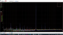
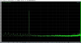
P.S. the latest update on a -6dB pcm 1KHz test signal, upsampled by HQPlayer @dsd512 to this 1 but balanced FF with a clock buffer behind it. Because it's balanced the 2nd order distortion might be a lot better than your first try with the 1 bit FF, but I'd have to verify to be sure.
Attachments
Hi mterbekke (I don't know your name ...):
... I'm a bit unsure of what you may mean here? Do you mean that you buffer the clock to the FF with a different brand clock buffer or do you let the FF do the low/high level DSD signal shifts and then you buffer this signal with a clock buffer (going towards the analog out)?
Hmmm ... interesting sentence. I haven't tried this yet but in my experience tuning the trace width & transmitting resistor in a digital signal "path" has much to say in terms of making the square wave not overshoot. Thus ensuring that overshoot signals are not transmitted to the PSU and decouplings - which I reckon may cause noise on the PSU as well as on the logic IC itself. Is this what you mean?
Personally I also believe that the ground bounce found on many/all logic ICs is a real "issue" in audio contexts. It might be feasible to parallel many logic outputs so as to not load the individual output beyond its "low-distortion limit", however, most logic ICs only have one ground pin which means that the inductive impedance of this pin - multiplied by the additional current running through the paralleled outputs - will cause a higher ground bounce. IMHO this is not insignificant.
I did a search a couple of years ago for a FF array with multiple GND pins and to my memory I found one with 32 FFs and multiple GND pins. But it was a BGA package - or something like that - so I couldn't just make out how to handle it in practice (and now I can't remember its type name).
BTW, according to a Japanese website, the 74LCX series has very evenly balanced output low/high levels at various current loads - thus not distorting that much when shifting high to low levels.
I don't know yet but I think there may be two options: diyinhk's presumably DSD1024 USB adapter and then I hope that Amanero's upcoming 768 kHz card may also be able to do so (see #2106 in this thread).
But from reading on audiophilestyle.com's forum some people there have succeeded in doing this - and actually also DSD2048. I assume one way to find out how it could be done may be to contact with these people but I just haven't had the time yet to do so .... Here is a link - #22 and #23:
Build a 100% Audiophile computer. - General Forum - Audiophile Style
That looks impressive for a single FF circuitry ... Just about -98 dB 3H level. Do you know why the noise "pins" at the other frequencies are there?
Cheers,
Jesper
and buffer that with a different brand clock buffer.
... I'm a bit unsure of what you may mean here? Do you mean that you buffer the clock to the FF with a different brand clock buffer or do you let the FF do the low/high level DSD signal shifts and then you buffer this signal with a clock buffer (going towards the analog out)?
but really low levels need manual tuning of the connection from FF to buffer as well as tuning power supply levels.
Hmmm ... interesting sentence. I haven't tried this yet but in my experience tuning the trace width & transmitting resistor in a digital signal "path" has much to say in terms of making the square wave not overshoot. Thus ensuring that overshoot signals are not transmitted to the PSU and decouplings - which I reckon may cause noise on the PSU as well as on the logic IC itself. Is this what you mean?
Personally I also believe that the ground bounce found on many/all logic ICs is a real "issue" in audio contexts. It might be feasible to parallel many logic outputs so as to not load the individual output beyond its "low-distortion limit", however, most logic ICs only have one ground pin which means that the inductive impedance of this pin - multiplied by the additional current running through the paralleled outputs - will cause a higher ground bounce. IMHO this is not insignificant.
I did a search a couple of years ago for a FF array with multiple GND pins and to my memory I found one with 32 FFs and multiple GND pins. But it was a BGA package - or something like that - so I couldn't just make out how to handle it in practice (and now I can't remember its type name).
BTW, according to a Japanese website, the 74LCX series has very evenly balanced output low/high levels at various current loads - thus not distorting that much when shifting high to low levels.
... That is also my impression. I am thinking that if it is possible to make something FPGA + discrete - well, with my knowledge that sounds particularly intriguing (albeit I don't know if this is what xx3stksm may be doing).I think xx3stksm is on a great path for that matter.
...Btw how or with what do you plan on getting dsd1024 out of your pc? I'd like to know, all I could find were usb adapters that needs a lot of software development to get it enabled.
I don't know yet but I think there may be two options: diyinhk's presumably DSD1024 USB adapter and then I hope that Amanero's upcoming 768 kHz card may also be able to do so (see #2106 in this thread).
But from reading on audiophilestyle.com's forum some people there have succeeded in doing this - and actually also DSD2048. I assume one way to find out how it could be done may be to contact with these people but I just haven't had the time yet to do so .... Here is a link - #22 and #23:
Build a 100% Audiophile computer. - General Forum - Audiophile Style
P.S. the latest update on a -6dB pcm 1KHz test signal, upsampled by HQPlayer @dsd512 to this 1 but balanced FF with a clock buffer behind it. Because it's balanced the 2nd order distortion might be a lot better than your first try with the 1 bit FF, but I'd have to verify to be sure.
That looks impressive for a single FF circuitry
... Just about -98 dB 3H level. Do you know why the noise "pins" at the other frequencies are there? Cheers,
Jesper
Last edited:
Over the years I have worked on many Discrete DAC designs – in fact I must confess my first “Real” DAC design (not just cobbling together a design based on Datasheet / Application Notes) was a Discrete DAC and at the time I had no idea what I was getting involved with – however it was a fundamental learning experience that all my designs since then still owe there genesis too – even 30 years later…
I must say its very educational to work with Digital Logic in an Analogue mode of operation (where the Analogue parameters of logic gate needs to be considered and understood).
Here are a few useful design points to consider when working with Logic Gates in Analogue operation (Sorry if these have already been discussed):-
1. For optimal measured performance, the lowest output impedance is important, however in balanced configuration, High / Low impedance matching is not so important as in balanced operation there is always a Pch (High) and Nch (Low) device in the signal path, then only during the H/L L/H switching transition period is the output impedance “undetermined” which is why the fastest Logic family is desirable (shortest edge transition times).
2. I’ve had best measured results with 74AC and 74VHC logic family – with the TinyLogic UHS being the best. TinyLogic offers the smallest package size (least internal inductance / lead resistance) fastest edges, lowest impedance and no internal gate cross modulation.
3. For best measured performance, the Resynchronization logic (D-Type FF) should be isolated from “Heavily” integrated audio PSU currents – so the outputs of the FF should be buffered.
4. For best measured performance, RTZ (Return to Zero) modulation should be implemented to insure the energy contribution (Error) of edge transitions is included for EACH clock cycle.
5. The loading of each output phase must be equal for lowest Even order distortion.
6. The Voltage coefficient of the output resistors in the LPF must be considered – the total Voltage coefficient of the DAC element (Gate impedance) and output resistors in the LPF will be seen as odd order distortion (Resistance value change over signal voltage swing). Operating in current mode ( Near Zero ohm’s seen at the Gate terminal mitigates the issue of DAC Element Voltage coefficient errors). For lowest VC, 0603 and 0805 resistors should be avoided – and Thin film resistors offer lower VC then Thick film resistors.
7. The Logic gate offers no PSRR, the PSU is in effect the DAC voltage reference, Noise and performance of these supplies is the foundation of the systems audio performance. Both Noise and Output impedance of the PSU should be optimized.
8. Clock – with the PSU, the Clock performance is the very heart of the system performance – with a 1 bit system, the clock will ultimately be the systems limiting “Analogue” factor.
Working with discrete DAC’s designs opens a complete bag of hurt – but nothing is more educational for a digital audio designer to understand and resolves these issues – its both frustrating but deeply satisfying when it all comes together _ sonically, nothing compares …
I must say its very educational to work with Digital Logic in an Analogue mode of operation (where the Analogue parameters of logic gate needs to be considered and understood).
Here are a few useful design points to consider when working with Logic Gates in Analogue operation (Sorry if these have already been discussed):-
1. For optimal measured performance, the lowest output impedance is important, however in balanced configuration, High / Low impedance matching is not so important as in balanced operation there is always a Pch (High) and Nch (Low) device in the signal path, then only during the H/L L/H switching transition period is the output impedance “undetermined” which is why the fastest Logic family is desirable (shortest edge transition times).
2. I’ve had best measured results with 74AC and 74VHC logic family – with the TinyLogic UHS being the best. TinyLogic offers the smallest package size (least internal inductance / lead resistance) fastest edges, lowest impedance and no internal gate cross modulation.
3. For best measured performance, the Resynchronization logic (D-Type FF) should be isolated from “Heavily” integrated audio PSU currents – so the outputs of the FF should be buffered.
4. For best measured performance, RTZ (Return to Zero) modulation should be implemented to insure the energy contribution (Error) of edge transitions is included for EACH clock cycle.
5. The loading of each output phase must be equal for lowest Even order distortion.
6. The Voltage coefficient of the output resistors in the LPF must be considered – the total Voltage coefficient of the DAC element (Gate impedance) and output resistors in the LPF will be seen as odd order distortion (Resistance value change over signal voltage swing). Operating in current mode ( Near Zero ohm’s seen at the Gate terminal mitigates the issue of DAC Element Voltage coefficient errors). For lowest VC, 0603 and 0805 resistors should be avoided – and Thin film resistors offer lower VC then Thick film resistors.
7. The Logic gate offers no PSRR, the PSU is in effect the DAC voltage reference, Noise and performance of these supplies is the foundation of the systems audio performance. Both Noise and Output impedance of the PSU should be optimized.
8. Clock – with the PSU, the Clock performance is the very heart of the system performance – with a 1 bit system, the clock will ultimately be the systems limiting “Analogue” factor.
Working with discrete DAC’s designs opens a complete bag of hurt – but nothing is more educational for a digital audio designer to understand and resolves these issues – its both frustrating but deeply satisfying when it all comes together _ sonically, nothing compares
…
Last edited:
I have been working with some true direct DSD circuits and , besides the remaining noise issues, my initial view is that here we are closer to what was recorded in the first place, regardless if it is vinyl rip or digital recordings.
+2
A true 1Bit ADC to DAC path is transparent to my ears
Any ADC kit for DSD with higher rates 128m 256, 512, etc.
Hi all (good morning, actually - it is morning here in Denmark)
@JohnW: Thanks for sharing your experiences with designing a discrete "no-dac" ... when reading your post I do, however, notice that you often write "best measured" performance which makes me think that you might be saying that you have found that there is a difference between best measured and best sounding performance ... ?
I also notice that you have found the tinylogic UHS to give the best results. Looking at the datasheets for a couple of these ICs I can see that design-wise they appear to be "related" to the LCX series that I mentioned in an earlier post because they (according to measurements on a Japanese website) should have a very balanced HIGH and LOW output impedance.
Have you BTW tried ECL logic? Mentioned here a couple of times and looking a bit into it in the last couple of days they appear to have advantages in terms of low PSU "disturbances" and potentially ultra-high bandwidth. I also did a simulation of a simple (differential basically) ECL circuitry and it had a 3.2 GHz bandwidth ....
@MarcelvdG & All here: I seem to remember that you, Marcel, in some thread here on diyaudio talked about a practical RTZ circuitry. I can't find it though - not least because diyaudio's search engine appears to have an error of some kind in terms of being able to find the "RTZ" term in a search ...
Also searching for an RTZ circuitry on the internet doesn't really bring up an actual practical circuitry ... this is to say that if one of you know of a link to an "audio-relevant" RTZ circuitry I'd appreciate seeing it
@merlin el mago: I am also not aware of any DSD diy ADC but in Marcel's ADC thread I mention the ADS1204 which likely will work at DSD512 with quite good specs (and only a second order modulator). But, again, IME the challenge is to get the data into the computer ... (but if someone could do this I would be fine with building an ADS1204 based ADC in a couple of weeks).
Cheers,
Jesper
@JohnW: Thanks for sharing your experiences with designing a discrete "no-dac" ... when reading your post I do, however, notice that you often write "best measured" performance which makes me think that you might be saying that you have found that there is a difference between best measured and best sounding performance ... ?
I also notice that you have found the tinylogic UHS to give the best results. Looking at the datasheets for a couple of these ICs I can see that design-wise they appear to be "related" to the LCX series that I mentioned in an earlier post because they (according to measurements on a Japanese website) should have a very balanced HIGH and LOW output impedance.
Have you BTW tried ECL logic? Mentioned here a couple of times and looking a bit into it in the last couple of days they appear to have advantages in terms of low PSU "disturbances" and potentially ultra-high bandwidth. I also did a simulation of a simple (differential basically) ECL circuitry and it had a 3.2 GHz bandwidth
.... @MarcelvdG & All here: I seem to remember that you, Marcel, in some thread here on diyaudio talked about a practical RTZ circuitry. I can't find it though - not least because diyaudio's search engine appears to have an error of some kind in terms of being able to find the "RTZ" term in a search ...
Also searching for an RTZ circuitry on the internet doesn't really bring up an actual practical circuitry ... this is to say that if one of you know of a link to an "audio-relevant" RTZ circuitry I'd appreciate seeing it
@merlin el mago: I am also not aware of any DSD diy ADC but in Marcel's ADC thread I mention the ADS1204 which likely will work at DSD512 with quite good specs (and only a second order modulator). But, again, IME the challenge is to get the data into the computer ... (but if someone could do this I would be fine with building an ADS1204 based ADC in a couple of weeks).
Cheers,
Jesper
Last edited:
... Oooups ....
I can feel that I have to modify this ... I have too much to do currently so I'd rather not take on more projects. But if someone can make what it takes to get the data into the PC I can - in due time - make the ADC based on the ADS1204 (should this be interesting).
Cheers,
Jesper
(but if someone could do this I would be fine with building an ADS1204 based ADC in a couple of weeks).
I can feel that I have to modify this ... I have too much to do currently so I'd rather not take on more projects. But if someone can make what it takes to get the data into the PC I can - in due time - make the ADC based on the ADS1204 (should this be interesting).
Cheers,
Jesper
So guys we need an USB interface can work any higher than 64. I will ask Domenico from Amanero to know if the new board to record music can support DSD.
I was actually thinking the same - good idea Felipe ;-)
Jesper
@JohnW: Thanks for sharing your experiences with designing a discrete "no-dac" ... when reading your post I do, however, notice that you often write "best measured" performance which makes me think that you might be saying that you have found that there is a difference between best measured and best sounding performance ... ?
I was trying to be careful here - a point that you correctly picked up upon , The sound quality of Analogue Master tape and good Turntables demostartes how bad the sound of PCM Digital is – although for so many years we have been told Digital is "Perfect"!I take offense when I'm quoted as being a “digital” designer – as “Digital” sounds so poor!
In all seriousness, I now appreciate a very important factor in audio reproduction that is little understood (and not just Audio) - and it will be very controversial. While I have a basic understanding of its effect I'd like to "properly" research it as my PhD studies - that is once I've completed a few projects I've been working on for far too long now. Once I've complete these designs I plan / hope to work with a UK university researching the effect (As an “Expert “ Research PhD – as I have no formal university education).
I don't want to publicly say much more at this time, only because experience has shown me that the world is full of those who try to claim others ideas as there own.. Obviously the research will be public, but there will be no question of its roots
I've had bitter experience over the years of others I've worked with (who have a greater egos and ability with communications) claiming my ideas / developments as there own...I also notice that you have found the tinylogic UHS to give the best results. Looking at the datasheets for a couple of these ICs I can see that design-wise they appear to be "related" to the LCX series that I mentioned in an earlier post because they (according to measurements on a Japanese website) should have a very balanced HIGH and LOW output impedance.
More important with the TinyLogic is the smaller/ lower package inductance's, No Gate cross modulation and high edge speeds.
As I mentioned before, in balanced operation difference in High / Low output impedance does not matter as there is always a Pch (High) and Nch (Low) device in the signal path. Even with decent matching in a single-ended system the H/L impedance matching will be still too poor to achieve todays “Low” THD...
Have you BTW tried ECL logic? Mentioned here a couple of times and looking a bit into it in the last couple of days they appear to have advantages in terms of low PSU "disturbances" and potentially ultra-high bandwidth. I also did a simulation of a simple (differential basically) ECL circuitry and it had a 3.2 GHz bandwidth
The trouble with is ECL logic is the low voltage level swings – combined with small geometry input devices in the input Diff pairs which result in high LF noise. With Audio the trouble is we need low phase noise across the audio Bandwidth – a unique requirement in the electronics industry... Communications and other industry's sectors don't care much about phase noise until about 12.5KHz...
Fast 5V CMOS logic (AC / VHC series) has the lowest phase noise I've measured. While the balanced operation of ECL is desirable – with tight / careful layout, CMOS gives better results – I use small 2:1 pulse transformers for Balanced CMOS to single-ended operation where critical clocks need to be distributed across a PCB with the lowest Phase noise.
@MarcelvdG & All here: I seem to remember that you, Marcel, in some thread here on diyaudio talked about a practical RTZ circuitry. I can't find it though - not least because diyaudio's search engine appears to have an error of some kind in terms of being able to find the "RTZ" term in a search ...
Also searching for an RTZ circuitry on the internet doesn't really bring up an actual practical circuitry ... this is to say that if one of you know of a link to an "audio-relevant" RTZ circuitry I'd appreciate seeing it
If you look at Marcel's ADC, you can see the 02 NOR Gates after the D-type FF and “Enabled” by the Clock performing the RTZ – although I'd expect to see AND / NAND Gates here??? (I'd need to simulate Marcel's design on paper to see whats going on here) – but typically I'd Logic AND / NAND the Data with Clock to form a RTZ “Gating” effect.
Last edited:
@MarcelvdG & All here: I seem to remember that you, Marcel, in some thread here on diyaudio talked about a practical RTZ circuitry. I can't find it though - not least because diyaudio's search engine appears to have an error of some kind in terms of being able to find the "RTZ" term in a search ...
Also searching for an RTZ circuitry on the internet doesn't really bring up an actual practical circuitry ... this is to say that if one of you know of a link to an "audio-relevant" RTZ circuitry I'd appreciate seeing it
You can indeed look at the feedback DAC in my DSD ADC, or at this DAC: 74AHC02 and 74AHC08 DAC with 97 dB(A) dynamic range This DAC actually has many of the features JohnW wrote about.
Hi Guys
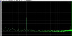
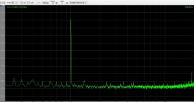
Here is the best result so far from a simple NoDac.
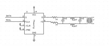
Amanero with ISO7640 after into a 74AUCiG flip flop and balanced out to C-L-C filter and trafo . Trafo has a 10K resistor as load.
Power supply is one LiFePo4 cell (3,3V) so the output is not very high, and that is one of the reasons for the relatively high noise floor.
Have only made it in the lab, quick and dirty, but with equally long mini coax cables from ISO7640 to Flip Flop. No sign of distortion in the -50 -60 levels
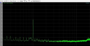
Here is the best result so far from a simple NoDac.
Amanero with ISO7640 after into a 74AUCiG flip flop and balanced out to C-L-C filter and trafo . Trafo has a 10K resistor as load.
Power supply is one LiFePo4 cell (3,3V) so the output is not very high, and that is one of the reasons for the relatively high noise floor.
Have only made it in the lab, quick and dirty, but with equally long mini coax cables from ISO7640 to Flip Flop. No sign of distortion in the -50 -60 levels
Attachments
Koldby,
Decent results for a simple solution
Your not returning to Zero, so I suspect the conversion error will take the form of white noise - maybe one of the reasons you have a high noise floor.
Whats your clock like? are you feeding your clock directly into the FF then the USB interface (so you Master clock is on the side of the FF?
Also the THD readings aer incorrect for the higher output levels, not sure whats going on there...
Last edited:
I am not sure I know what return to Zero means. The high noise floor is there even when the NoDac is turned off. My clock comes from the Amanero USB interface. The THD readings have never been reliable on this software FFT analyzer. The thing is, I have measured with the same equipment on quite a few NoDac solutions and they ave all shown high levels of harmonics @ -50 and -60 dB, but this in implementation the harmonics are all gone.
I have not been able to listen to it yet, so I don´t know if the noise is still at an annoyingly high level.
I have not been able to listen to it yet, so I don´t know if the noise is still at an annoyingly high level.
Hello Koldby,
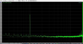
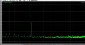
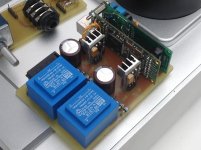
i have with amanero and isolator board much better figures, almost -100db THD +N. How do you have layout your power supply. It is important to disconnect power at USB side and use own powersupply. Further use seperate powersupply at output side of isolator board. Both may be also batteries. but seperate not one battery.
i have with amanero and isolator board much better figures, almost -100db THD +N. How do you have layout your power supply. It is important to disconnect power at USB side and use own powersupply. Further use seperate powersupply at output side of isolator board. Both may be also batteries. but seperate not one battery.
Attachments
Last edited:
Hello Koldby,
i have with amanero and isolator board much better figures, almost -100db THD +N. How do you have layout your power supply. It is important to disconnect power at USB side and use own powersupply. Further use seperate powersupply at output side of isolator board. Both may be also batteries. but seperate not one battery.
Can you upload the measurements?
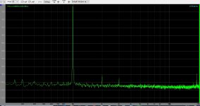
As I see it, the pics I showed had, besides some hum and harmonics of that , noise more than 100dB down.
But I agree with you , that maybe I could get some better figures if I supplied the Amanero (and that side of the isolator) with a seperate battery. Of course the PS for the DAC (and that side of the isolator) and the Amanero should not have the same battery. The isolator would have no effect otherwise.
One more thing, you have a very nice and clean layout , whereas my setup is a dirty and quick setup just to see how the 74AUC1G would work with an isolator board and differential output. The way my measure setup works also leaves a lot to be desired.
The main reason for uploading the pics, was to show , that the -50 and -60 dB measurements were MUCH cleaner than any of the other NoDac I have tried before.
The main reason for uploading the pics, was to show , that the -50 and -60 dB measurements were MUCH cleaner than any of the other NoDac I have tried before.
- Home
- Source & Line
- Digital Line Level
- The Best DAC is no DAC