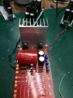
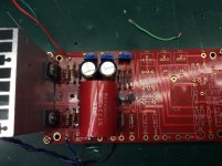
Wise advise, Jim. Thank you. I'll take it slow!
As an aside, and just so I understand for down the road: It looks to my neophyte eyes like the Glassware Dual/Bipolar Reg can be configured to, in effect, be two PSU boards. Am I completely off on that reading?
And finally, one more question about C3 before i start soldering: what's the range of capacitance that can work for that cap? I got a pair of these Cornell Dubliner 4.7uFs to use. Is that too far off the recommended 10uF or will they work?
Thanks for all the help!
Regarding the output capacitor...it determines the cut-off frequency (and blocks DC). The value will depend on the input impedance of the power amp following the preamp. Here's a calculator where you can determine the cutoff frequency for your application:
Coupling Capacitor Calculator by V-Cap
Regarding the output capacitor...it determines the cut-off frequency (and blocks DC). The value will depend on the input impedance of the power amp following the preamp. Here's a calculator where you can determine the cutoff frequency for your application:
Coupling Capacitor Calculator by V-Cap
Thanks so much Hikari1! This does more than answer my question - it helps me understand more about the function of the output cap. Very cool calculator and helpful explanations on that page. Based on my calculation for use with the ACA (10 Kohms), it looks like 4.7uF is a little low for C3.
Thanks so much Hikari1! This does more than answer my question - it helps me understand more about the function of the output cap. Very cool calculator and helpful explanations on that page. Based on my calculation for use with the ACA (10 Kohms), it looks like 4.7uF is a little low for C3.
It will play music and sound fine w/4.7uF into a 10K amplifier...but you may always wonder if you are missing some low frequencies.
But it will do no damage to use 4.7uF...if you don't have speakers that go that low, or play vinyl you might not have frequency response that low anyways.
so, i have finished a Salas SSLV 1.3 dual power supply. Im going dual mono. However some doubts are still bugging me. I have one positive and one negative regulator for each transformer. They are independent, dont share the ground conection, but they will when they are conected at the BA3. If i have a negative and a positive with common ground at the pre, wont they cancel themself?
And another question:
Im want to put both PSU in a single separated chassis and then feed the pre in another case. DC voltage will travel along a 40cm cable...any problem here?
Thanks
And another question:
Im want to put both PSU in a single separated chassis and then feed the pre in another case. DC voltage will travel along a 40cm cable...any problem here?
Thanks
The psu boards and toroid will be in one case, and the Ba-3 with input selector on the other case. I intend to transport DC voltage between cases (is that a bad idea?).
The other problem is the psu connection to the ba3. I have the Salas SSlv 1.1. it was connected like a battery (two positive reg's with common ground to make a 0 point and create a + and - sides) to my BA3. But now, with dual mono im not sure. But my dummy feelings tell me that i need to do the same ....maybe
Thank you for your help


picture hosting websites free
The other problem is the psu connection to the ba3. I have the Salas SSlv 1.1. it was connected like a battery (two positive reg's with common ground to make a 0 point and create a + and - sides) to my BA3. But now, with dual mono im not sure. But my dummy feelings tell me that i need to do the same ....maybe
Thank you for your help


picture hosting websites free
rectify it locally then let travel
Locally, you mean in the trafo case, and then make it travel to the pre amp case? if so, whats the best way to do it? Only bridge rectifiers? like the ones in F5 amps and others?
Locally, you mean in the trafo case, and then make it travel to the pre amp case? if so, whats the best way to do it? Only bridge rectifiers? like the ones in F5 amps and others?
only bridge rectifiers , you can use smaller ones - those plasticky blocks of 5A or so
MOSFET VGS on question.
I have a question about the turn-on voltage of the MOSFETs.
My + and - voltages are at 25.2 v and I have 25.2 volts on the source of Q3 I can adjust my 500r pot to achieve 20.8 on the gate. I tested my MOSFETs and the VGS on for the 2SJ313 is 2.91 and the 2sk2013 is about 3.5v. The voltages on Q4 are almost identical, however, my MOSFETs are not turning on and I have no voltage drop across R10 or R11?
I do have the correct 8ma through the input R6 and R7 resistors.
I'm not sure why the MOSFETs are not yet turning on? Do they need more of a voltage drop? I thought the VGS on was the voltage difference it needed to turn the FETS on?
I appreciate any guidance you guys can provide.
- Home
- Amplifiers
- Pass Labs
- The BA-3 as preamp build guide

