Thanks, I understand the diagrams. It is what I did for the primary. The issue for me is how to identify which pair of secondaries pertain to what winding. Other transformers have 4 different colors and, thus easy to identify. Antek has 2 pairs with the same colors. Maybe there is some kind of mark to identify the windings, I'll take a closer look.
Pass DIY Addict
Joined 2000
Paid Member
You should be able to measure it with your dmm and the diagram, it should not be blowing fuses.
A 1A fuse, especially if it is a fast-blow, will not be enough to energize the transformer on power up. A 1A slow-blow is likely to work better. Another option is to put a CL-60 thermistor on the hot leg of primary.
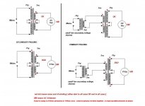
You should also tightly twist all wires that carry AC voltages. This means twisting the red and black primary wires together as well as twisting the green/blue pairs together. This minimizes the radiated energy from these wires. You'll want to mark your secondary pairs before you twist them, so you don't mix them up.
The secondary wires should be colored, in order: blue, green, blue, green. Each blue-green pair is a separate secondary. If you are creating dual mono, keep each secondary apart from one another. If you are creating a single pos - 0v - neg power supply, connect the "inner" blue-green" pair together to form the 0v reference point.
Last edited:
On Antek transformers the phasing of the primaries is indicated on the label. If you wish to see which secondary relates to which primary, follow post #7 in the thread below.
How to determine phase of transformer secondaries?
nash
How to determine phase of transformer secondaries?
nash
Pass DIY Addict
Joined 2000
Paid Member
Using a wall-wart is an EXCELLENT suggestion! Someone suggested this to me as I was restoring a piece of tube gear with a transformer that produces 200+ volts from household mains. Powering up with a 10Vac transformer instead of 120Vac is INFINITELY more safe as resulting voltages were more like 20-30v instead of 200-300v.
Failing at Bias attempt...
Board voltage +23.8 and -23.8v where they should
Turn on with the 25w bulb procedure, turns on on turn on and goes off immediately.
'been dialing P1 and P2 for the last half hour and all the meters staying at zero. First time I'm doing this kind of setup, so don't really know in what directions should I turn the pots, I guess I don't have the feel for it yet.
Mosfets are P20 and N30 from Digikey
Jfets are J74 and 170 matched from Hong Kong seller Punkydawgs, supposedly reputed.
Mosfets heatsinks not getting hot at all, is this normal?
Is it the 500 ohm trimpots, should I get the 1000 ohms's. Although it is strange that any response is apparent.
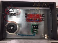
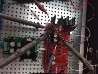
Basically only power connections to the board as seen on photo.
Inputs are shorted as also seen on the photo.
I shall appreciate any help as always.
Board voltage +23.8 and -23.8v where they should
Turn on with the 25w bulb procedure, turns on on turn on and goes off immediately.
'been dialing P1 and P2 for the last half hour and all the meters staying at zero. First time I'm doing this kind of setup, so don't really know in what directions should I turn the pots, I guess I don't have the feel for it yet.
Mosfets are P20 and N30 from Digikey
Jfets are J74 and 170 matched from Hong Kong seller Punkydawgs, supposedly reputed.
Mosfets heatsinks not getting hot at all, is this normal?
Is it the 500 ohm trimpots, should I get the 1000 ohms's. Although it is strange that any response is apparent.
Basically only power connections to the board as seen on photo.
Inputs are shorted as also seen on the photo.
I shall appreciate any help as always.
Attachments
Get 1k trimpots. 500ohm is not enough for fairchilds..Board voltage +23.8 and -23.8v where they should
Turn on with the 25w bulb procedure, turns on on turn on and goes off immediately.
'been dialing P1 and P2 for the last half hour and all the meters staying at zero. First time I'm doing this kind of setup, so don't really know in what directions should I turn the pots, I guess I don't have the feel for it yet.
Mosfets are P20 and N30 from Digikey
Jfets are J74 and 170 matched from Hong Kong seller Punkydawgs, supposedly reputed.
Mosfets heatsinks not getting hot at all, is this normal?
Is it the 500 ohm trimpots, should I get the 1000 ohms's. Although it is strange that any response is apparent.
Basically only power connections to the board as seen on photo.
Inputs are shorted as also seen on the photo.
I shall appreciate any help as always.
- Home
- Amplifiers
- Pass Labs
- The BA-3 as preamp build guide