Does that apply to a parallel connection of secondaries? There are 8 of them in LL1623, and to accomodate a range of Z's I need 3, 6, 7, or 8. Loose secondaries are not recommended by the application note, parallel connection is. Will there be any negative effect in sound quality due to that? (excluding all possible issues with commutation for simplicity) Looking at commutation circuit, I think of parallelling all the unused secondaries. For example, for 38Ω six secondaries must be in series, which leaves three that must be paralleled. Any comment on that?
Also, if an odd Z is shunted gently to match it to the nearest value, i.e. 300Ω to 64Ω, with the same power in the secondary, would there be any negative effect in sound? For example, 4W maximum output at 64Ω (16V) splits as 0.85W at 300Ω headphone and 3.15W at 81Ω shunt -- more than enough power for Sennheiser HD6x0, or a total loss of hearing, so the useful maximum power level would be lower by a multiple, at least by 2.
Lundals datasheet just make me scratch my head, can't help but think a single purpose wind would be beter than a transformer that has so many configurations, p-p, se, 8 secondaries, just goes against what I remember learning in physics 25 years ago wrt to efficiency, capacitance, inductance losse, etc. But I've never heard one so I am just whining.
The amorpous LL1623 looks like it would be the pick of the lot for a headphone transformer, the iron version have power spec's way higher than needed for headphones, and this I am not sure is good. In general the smaller the transformer the better.
This is what I see as a good PX4 design:
PX4 audio tube or valve, single-ended and push-pull amplifier designs
In case you haven't noticed I still favor DC coupling as with the original all DHT headamp (first post.)
The fault with the PX4.org design of course is the 6922 gain/driver. For my needs driving a PX4 or 307A with a med-low mu DHT, like the 4p1l just isn't to give any more power than a WE437 spud type amp and the linearity will be worse. A 4p1l to 4p1l makes a little more since, really gives more power than a 4p1l-307a (sans preamp), but perhaps not enough to make it worthwhile as in allowing me a greater range of headphone choices. Some may be happy with a spud a spud DHT amp with a big tube like the Selveta SV572-30 or the EML 30A.
We need a gain of at least 25 for a 2 stage PX4/307A amp to drive modern ortho headphones. I ask why do we want an all DHT headphone amp? For linear tubes of course.
The only small DHT I know of with a gain over 20 is the sulphur tube 841, it doesn't look all that linear and finding one seems difficult. There is also a really hard to find DHT called the KC3
Perhaps we change the scope a bit and allow an indirect heated triode of high quality. What would be the choice? We would want something obviously more linear than the 6dj8/6922. I've been eyeing the Ecc40 and E182CC.
I don't think a DHT with a mu of 25-30 will be much more linear than a tube like the E182CC or the Ecc40 ?
Yes but a E182CC has a better or tighter spec for mu of 25. If one were to buy a few dozen 6n6p's then one could find a E182CC "quality" tube. I suspect this to be the main reason Mog's tests weren't too good for the 6n6p. Lyn olsen points to these tube types as being most linear of the later era vs the 6dj8/12au7's. The spice models show they have highish 2H low 3H and luckily in a 2 stage amp the 2H gets cancelled out to a significant degree.
I have some good news. I have a response back from Magnequest that they can do a run of transformers with a 32 or 38 ohm secondary. And they can waive the extra $100 setup fee if there is enough interest.
I really can't rule out parafeed at this point, we see that Tribute started another thread for P-P the main reason being that the core of the transformer needs to be high permeable/high quality. One way around that and stay SE is a magnequest nickle core parafeed design. Even with the $100 surcharge their pricing is pretty good and they have a great reptation.
On a side note I was comparing tube curves of the P4/307A/2A3/Ad1. First thing is the 307A triode has a much higher Rp than a PX4 at ~1300 ohms, a true Marconi PX4 has an Rp ~800 ohms. Now the funny part is that the Sophia electric PX4 has an Rp of 1300, while the KRPX4 is ~1k. The closest modern tube to the PX4 is actually the Sophia "mesh" 50 with a Rp ~800 gain 5 and the EML AD1. Its really odd how modern tube manufacturers come up with tubes have no technical resemblance to the original other than base and heater voltage.
Makes one want to use available and known quality constructed tubes like the 6S4S or parallel 4P1l's for the outut and foorget about-it.
For the output we need to a descicion do we want a 5kish primary or a 2.5k kish primary.
If we are dealing with the 2A3/6S4S vs the PSE 4p1l we could run them at 5k primary and this would allow those wanting to use a single 4P1l or 307A, but we give up the advantages that come with a lower turns ratio.
as far as the secondary for this amp we really don't need a 300 ohm primary. There really aren't any low efficient 300 ohm headphones that couldn't be powered with a parallel resistor to load the primary, yea we are running the tubes a little harder but its not much. I think a single primary is going to give a better wind than multiples and adding taps is probably not smart..
Last edited:
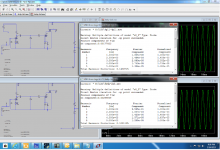
This is a simple spice comparison of a 4p1L to 4p1l 5k:40 OPT vs a 6n6p to 2A3 same OPT.
I know the concern is low level distortion and the thought that a very linear valve like the 4P1l will give better performance. Two simulations run exactly the same for a 1Vpk output. The result is that the 6n6p to 2A3 gives lower distortion at this low level (the difference is really neglible.) The point being that the distortion charateristic of a DHT output SET will be transformer dominated and selecting valves based on Moglaa's THD tested although somewhat useful doesn't really give a wholistic picture of a completed amplifier. BTW a 6C45p-2A3 had three times the distortion.
I know the concern is low level distortion and the thought that a very linear valve like the 4P1l will give better performance. Two simulations run exactly the same for a 1Vpk output. The result is that the 6n6p to 2A3 gives lower distortion at this low level (the difference is really neglible.) The point being that the distortion charateristic of a DHT output SET will be transformer dominated and selecting valves based on Moglaa's THD tested although somewhat useful doesn't really give a wholistic picture of a completed amplifier. BTW a 6C45p-2A3 had three times the distortion.
Attachments
Last edited:
EML AD1. Its really odd how modern tube manufacturers come up with tubes have no technical resemblance to the original other than base and heater voltage. Makes one want to use available and known quality constructed tubes like the 6S4S or parallel 4P1l's for the outut and foorget about-it.
If NOS tubes are used, one can never forget about it. If they are available today, they will be hard to replace a few years later, and if they are hard to get today, they will be extinct then. So for myself I accepted the reality and consider only new DHT power tubes. EML AD1 and EML 2A3mesh are very close in parameters (except the heater, which is not a problem with regulators), and EML's business seems to be goind well. Even if they do go under and their AD1 goes with them, 2A3 will be replaceable from other sources. I do not think 4P1L is still in production, hardly in any legacy equipment still in any use, and NOS stocks may suddenly dry up as they did with "1578 MELZ" (hi-rel Russian 6SN7 version from 50's): a few years back those were available, now only a few remain, mostly locally in Russia. So forgetting about it is not an option for a new amp design.
What is an option is a DAC directly driving the grid of power DHT. One DHT instead of two solves the problem of interstage coupling capacitor or transformer, may have better linearity, and definitely reduces the BOM, in particular eliminating NOS driver tube. If power DHT is a 2A3 variant, it will be manufactured for quite some time by a number of sources, so it is a prudent choice with all else more or less equal.
I am not stepping on anyone's preferences, but like it or not we are in 21st century, and while DHTs will go on, analog sources may and should go extinct for their fundamental failure to preserve music incorrupt forever. When that happens, DAC-to-DHT will be an obvious choice, as DAC can make +4.5V as well as it can make -45V. So that leap may as well be made now and save the troubles of driver stages, line inputs and the rest of it. For myself I have already made those choices: digital inputs only, new DHTs only, and uncompromising SS power and supporting circuits.
And one more thing has to be said about SS power. While people marvel at their mesh rectifiers (yes, they are worthy of marvelling at), the power grid voltage goes up and down far wider then DHT heaters are designed to survive, so the tubes are being quietly tortured to early death. (That is why EML's business will go well and ensure availability of replacements, which also explains their tensly cautious response to Rod's heater.) Heater regulators and HV regulators can and should be used to stabilise the voltages, but if that step is made, why bother staying with 50/60Hz grid at all? There is an option to AC-DC into 48V unstabilised, then DC-DC to any and all DCs required -- at a much higher frequency (i.e. 100kHz), where inductors are much smaller, capacitors are much smaller and so can have better dielectrics, EMI shielding is easier, and all harmonics are at least an order of magnitude above audio spectrum. Any comments on this?
Last edited:
If NOS tubes are used, one can never forget about it. If they are available today, they will be hard to replace a few years later, and if they are hard to get today, they will be extinct then. So for myself I accepted the reality and consider only new DHT power tubes. EML AD1 and EML 2A3mesh are very close in parameters (except the heater, which is not a problem with regulators), and EML's business seems to be goind well. Even if they do go under and their AD1 goes with them,
And one more thing has to be said about SS power. While people marvel at their mesh rectifiers (yes, they are worthy of marvelling at), the power grid voltage goes up and down far wider then DHT heaters are designed to survive, so the tubes are being quietly tortured to early death. (That is why EML's business will go well and ensure availability of replacements, which also explains their tensly cautious response to Rod's heater.) Heater regulators and HV regulators can and should be used to stabilise the voltages, but if that step is made, why bother staying with 50/60Hz grid at all? There is an option to AC-DC into 48V unstabilised, then DC-DC to any and all DCs required -- at a much higher frequency (i.e. 100kHz), where inductors are much smaller, capacitors are much smaller and so can have better dielectrics, EMI shielding is easier, and all harmonics are at least an order of magnitude above audio spectrum. Any comments on this?
I wasn't clear enough, the AD1 was the closest to the original, it was the sophias I was knocking, it really looks like they tried to make a PX4 but could only get it to work with a 7.5V filament so called it a 50 , and vice-versa with their "PX4". All I am saying is that many of the new tubes aren't what they are "named" which isn't a problem for a careful diyer but I wouldn't count on any PX4 being made in 2020 there just can't be any profit, I mean right now no one really makes a PX4. I personally wouldn't invest in a new dht that isn't a popular model, ie 2a3, 300B, etc.
I agree fully about the DAC, there are some excellent solid stage analog stages and there is nothing wrong with adding a little jfet gain to help keep the power amp to 2 stages. But I don't agree that there is any DHT's with a gain over 15 that we would still need that offer any improvement in linearity over the 5687/6n6p tube type when analyzing the amplifier as a whole (instead of isolated sections of the amp.)
As far as high frequency filament regulation, its not AC, its not a sine wave, its noisy triangle/sawtooth waves. Its just too convenient to use a coleman reg for a DIYer at this point than to mess with something that can go terribly wrong without the proper equipment to develop it, sort of out of scope imho.
On another subect its been said that two 8 ohm secondaries in series and center tapped to ground, impedance match to a balanced drive 32 ohm headphone. I've been trying to simulate this and its not showing to be true at all?
I wouldn't count on any PX4 being made in 2020 there just can't be any profit
It can and has been done, but only with vertical integration. EML made their AD1 in apparent alliance with Yamamoto that plugged it into his amp line, and so the EML's brand and Yamamoto's brand combined put AD1 on top of the price list. KR Audio made their big "KRT1610" tube and "Kronzilla" amp based on it, which cost a small fortune, but it is there, it has been done. They also have "PX4" and a number of far more obscure tubes, including a clone of the very first ones. As they are hand made, no assembly line to ammortise, they can recreate any design within their present range of materials, skills and equipment. I am actually surprised EML doesn't make a 101D/104D/205D ball tube clone for Yamamoto's amps.
It can and has been done, but only with vertical integration. EML made their AD1 in apparent alliance with Yamamoto that plugged it into his amp line, and so the EML's brand and Yamamoto's brand combined put AD1 on top of the price list. KR Audio made their big "KRT1610" tube and "Kronzilla" amp based on it, which cost a small fortune, but it is there, it has been done. They also have "PX4" and a number of far more obscure tubes, including a clone of the very first ones. As they are hand made, no assembly line to ammortise, they can recreate any design within their present range of materials, skills and equipment. I am actually surprised EML doesn't make a 101D/104D/205D ball tube clone for Yamamoto's amps.
KR's "PX4" has an Rp almost 20% greater than the originals, they can call it whatever they want but it isn't a PX4, its a tube made by KR called a PX4.
If NOS tubes are used, one can never forget about it. .....<snip>
What is an option is a DAC directly driving the grid of power DHT. One DHT instead of two solves the problem of interstage coupling capacitor or transformer, may have better linearity, and definitely reduces the BOM, in particular eliminating NOS driver tube. If power DHT is a 2A3 variant, it will be manufactured for quite some time by a number of sources, so it is a prudent choice with all else more or less equal.
I am not stepping on anyone's preferences, but like it or not we are in 21st century, and while DHTs will go on, analog sources may and should go extinct for their fundamental failure to preserve music incorrupt forever. When that happens, DAC-to-DHT will be an obvious choice, as DAC can make +4.5V as well as it can make -45V. So that leap may as well be made now and save the troubles of driver stages, line inputs and the rest of it. For myself I have already made those choices: digital inputs only, new DHTs only, and uncompromising SS power and supporting circuits.
That looks like a good manifesto.
Direct-from-DAC will work very well, with current-output DACs.
The open-loop JFET shunt-cascode circuit posted earlier has been developed further to drive a 2A3 grid to full power (yes, +/- 50V) from +/-2mA - at distortion level of 0.05% - with distortion falling with signal level.
It has tiny distortion because the I to V is simply a resistor; the remaining circuit performs dc level-shifting and current-steering only. This circuit would seem to be ideal for Phil's PCM1794 (3.9mA @ 0dB).
DACs like PCM1794 also give differential current outputs, so a PP 2A3 can be driven to full power be using 2 of these little circuits. No splitter, no interstage transformer - direct to PP grids.
Any DHT needing -50V bias or less can slide in, without change to the driver circuit - other than the current-sense resistor.
I can post the update when I am back at my workstation, if anyone is interested in the circuit.
.
Yes this applies to the secondary too but you have to divide by a factor equal to the turn ratio. It is a much smaller effect and in practice is negligible. More importantly you have to consider that the transformer has been designed to work like that (i.e. primaries always in series and secondaries in series-parallel combinations).
I am looking at the exploding numbers of relays for secondaries' commutation. If instead of paralleling the unused ones they are simply connected in series and commutated as in a stepped volume control, there would be only 4 relays. But will that 'loose end' in the secondary affect the sound? For example, for 8Ω speaker only 3 out of 8 secondaries will be used, the other 5 connected in series would be a 'loose end'. For headphones the loose end is no more than 2 out of 8.
For uncompromising paralleling, it will require 2 SPDT relays per coil group per configuration, so 4 groups (3 + 3 + 1 + 1 secondaries) and 4 configurations (8, 7, 6 and 3 secondaries in series) requires up to 32 relays, or even 64 if SPST type is used. The incentive to use only 4 of SPST type could not be more compelling, even in a design for fanatics by fanatics. Capacitance in all this wiring would also add up.
I can post the update when I am back at my workstation, if anyone is interested in the circuit.
Please do.
For those of us with big LP collections, the Analogue signal chain can exist in parallel, and switch-in at the output DHT's grid, if required.
LPs wear out with each use, so digitising them into FLAC file would be the best way to preserve music. If not, an ADC inside the LP player would still be a better option that avoids adding noise and picking EMI through analogue interface. But my concern is mostly about analogue signal level the amp has to raise to a precisely set grid voltage. With DAC, the maximum signal level is set at design stage. Therefore amplification to grid level is also set precisely, and the tube is perfectly controlled. If the signal comes from outside, its maximum level is unknown (black boxes, loosely implemented standards), so how would one set amplification value to get the right grid voltage range? (rhetorical question)
But will that 'loose end' in the secondary affect the sound? For example, for 8Ω speaker only 3 out of 8 secondaries will be used, the other 5 connected in series would be a 'loose end'. For headphones the loose end is no more than 2 out of 8.
I have never tried but I think it will cause a clearly bad effect. Using only 3 out of 8 secondaries you have a big insertion loss, in the best case. Having no feedback you can have the secondary floating. Then if the unused secondaries will have other effects I don't know. I would use an OPT which is at least optimized for loudspeakers.
Actually I often have the secondary floating because I have found that in many cases this gives an extended frequency response in comparison to a grounded secondary for certain winding geometries.
I have never tried but I think it will cause a clearly bad effect. Using only 3 out of 8 secondaries you have a big insertion loss, in the best case.
Let me clarify with a schematic. Speaker (8Ω) is switched on by relay Sz1 -- it needs 3 secondaries. Headphones with different Z (32, 38, or 64Ω) switched by relays Sz2...Sz4 (6, 7 or 8 secondaries), and odd Z's (52 or 300Ω) are additionaly shunted by Rs1 or Rs2 with relays Ss1 or Ss2. A microcontroller runs all relays, so at any time this circuit is configured for only one Z value. Commutation is done at zero input signal (shorted DAC output), so there is no current in the secondary during commutation. Where would be the loss you mentioned? The part of the secondary that is disconnected (upper loose end) has infinite load resistance and zero current through it, therefore no AC energy can be lost in there by conduction. It may have some influence via capacitance -- that I do not know how much, but a typical reed relay is designed for GHz AC commutation with appropriately low capacitances. All AC energy that goes into transformer's primary will come out of the loaded section of the secondary, with 64Ω load at most, as there is nowhere else for it to come out from. Please tell me which mechanism of losses I am missing here.
Attachments
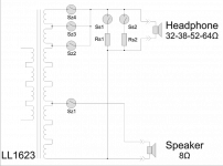
Let me clarify with a schematic. Speaker (8Ω) is switched on by relay Sz1 -- it needs 3 secondaries. Headphones with different Z (32, 38, or 64Ω) switched by relays Sz2...Sz4 (6, 7 or 8 secondaries), and odd Z's (52 or 300Ω) are additionaly shunted by Rs1 or Rs2 with relays Ss1 or Ss2. A microcontroller runs all relays, so at any time this circuit is configured for only one Z value. Commutation is done at zero input signal (shorted DAC output), so there is no current in the secondary during commutation. Where would be the loss you mentioned? The part of the secondary that is disconnected (upper loose end) has infinite load resistance and zero current through it, therefore no AC energy can be lost in there by conduction. It may have some influence via capacitance -- that I do not know how much, but a typical reed relay is designed for GHz AC commutation with appropriately low capacitances. All AC energy that goes into transformer's primary will come out of the loaded section of the secondary, with 64Ω load at most, as there is nowhere else for it to come out from. Please tell me which mechanism of losses I am missing here.
Insertion loss is a direct consequence of not using all secondaries. It has nothing to do with relays. You just have more DC resistance in comparison to the primary impedance. It just means that your OPT is less efficient and less power is transferred from the primary to the secondary. In the case of the LL1623 connected as specified for 5.6K/8R you have 26.8 turn ratio so Zp= (26.8*26.8)*8= 5746 ohm, the primary DC resistance is 164 ohm and the secondary DC resistance seen from the primary is 0.2*(26.8*26.8)= 144 ohm.
This looks ideal because the two DC resistances are very similar which usually means that about half of the winding volume has been used for the primary and half for the secondary. This is the choice for minimum losses.
Actually you might want the secondary DC resistance a bit lower because choosing a thicker wire for the secondary you compesate its higher AC resistance (skin effect) at high frequency.
So the total DC resistance at the primary is 164+144=308 ohm. And the total is 6054. Thus the efficiency of the transformer is 5746/6054= 95% (or about 0.2 dB power loss as specified). If you only use 3 secondaries in series the secondary DC resistance seen from the primary is (0.4*3)*(26.8*26.8)= 862 ohm which means an efficiency of 85% (or a power loss of 0.7 dB). This is usually the efficiency of cheap transformers.
Other non desirable effects are not easily predictable. Maybe you won't have any.
About the sound you can only tell by listening.
Insertion loss is a direct consequence of not using all secondaries. .
You describe much better my concerns wih the lundahl transformers much better than i was. Insertion loss with headphones is a big deal.
I can't get the simulations to prove it but I was told for example a 5k transformer with two 8 ohm secondaries in series and the center grounded hooked up in balanced config to a 32 headphone would work to give a 5k:32 ratio. The same follows that two 75 ohm secondaries would give a 5k:300 balanced output. I can't explain the math either or get simulation to prove it..
But evidently this is how some of the commercial DHT headamps are configured.
If you only use 3 secondaries in series the secondary DC resistance seen from the primary is (0.4*3)*(26.8*26.8)= 862 ohm which means an efficiency of 85% (or a power loss of 0.7 dB). This is usually the efficiency of cheap transformers.
Other non desirable effects are not easily predictable. Maybe you won't have any.
Thanks. I'll have to read it a few more times and think about it for a while, but I already see it comes down to a compromise. The 8Ω speaker is a secondary priority in a headamp, so headphones come first, and 6~8 secondaries out of 8 does not seem to be a problem. The 8Ω can be accomodated by paralleling of 3+3 secondaries -- it will add 2 SPDT relays (or 4 SPST). In that case 6 will be the least number of secondaries used with any load, and for 38Ω it will be 7. An alternative to that is 1) a maze of relays for ideal paralleling or 2) a magical custom transformer that somehow takes all loads from 8 to 64Ω or 3) hard shunting of headphones and higher distortion or 4) simplification of requirements (i.e. surrender). Out of these, I take a small extra loss of transformer efficiency if that doesn't spoil the sound. After all, design of a 4W DHT class A headamp is not oprimised for transformer efficiency at the expense of everything else in the specification. I knew the transformer will be the hardest part of this design.
Out of these, I take a small extra loss of transformer efficiency if that doesn't spoil the sound. After all, design of a 4W DHT class A headamp is not oprimised for transformer efficiency at the expense of everything else in the specification. I knew the transformer will be the hardest part of this design.
My experience is this is the wrong direction. I just don't want to see you take the wrong directions I have taken. The OPT is the most important piece of the puzzle.
Before building a headphone amplifier it should be a pre-requisit to read dsavisk's website ecp audio diy: Designing a Parafeed Headphone Amplifier.
On a positive not I've been listening to my HE-500 orthos with my WE417 SET. This has a single feed Electraprint transformer that is about 80% efficient, it sounds no where near as good as Dsvask's parafeed implementation of the same basic spud concept. It is also very under-powered for the HE-500's as is the SHA-1. But at lowish volumes it sounds better than a Lyr (push-pull mosfet hybrid.)
So I am optimistic that an SET is still the best direction to take.
You may want to look closely at the Sowter headphone opt's before buying a big 50W lundhal made for speakers.
BTW I've been simulating various configurations of 4p1l and 2A3 2 stage amplifiers, basically finding that the overal linearity of the input tube is not as important as the 3H level. In other words its much better to have a valve with a higher THD that is predominately 2H than one that is lower THD but has significant 3H, this is because the output tube cancels some of the input tube's 2H distortion. I can summarize the spice data if there is interest.
The age old practice of "pentode IN - triode OUT" or "triode IN - pentode OUT" is what sounds best to my ears because (I think) of the balance of harmonics.
Of course it doesn't always work. With a 4P1L pentode IN and 4L1P triode OUT all I got was much more distortion, mostly odd order. It didn't sound great. That may be due to my implementation of the 4P1L in pentode mode, I don't know.
Of course it doesn't always work. With a 4P1L pentode IN and 4L1P triode OUT all I got was much more distortion, mostly odd order. It didn't sound great. That may be due to my implementation of the 4P1L in pentode mode, I don't know.
- Home
- Amplifiers
- Tubes / Valves
- The all DHT SET Headphone Amp