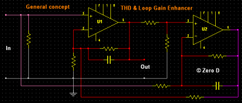
The following is applicable to both Power Amps & OpAmps.
I've been tinkering for a number of weeks with an "Enhancer" circuit added to an Amp, which improves both the THD & Loop Gain specs. I'd be interested in hearing your comments & suggestions etc, for where it "might" be improved etc.
Harry Dymond has been kind enough to assist me in various ways") & by simulating the circuit & establishing that it improves the Loop Gain. He also provided me with several links http://www.analog.com/static/imported-files/application_notes/AN-107.pdf
& by simulating the circuit & establishing that it improves the Loop Gain. He also provided me with several links http://www.analog.com/static/imported-files/application_notes/AN-107.pdf
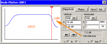
I also observed greater bandwith with my Enhancer circuit, as in AN-107.
Figure 1 in AN-107
That arrangement seems different to mine.
Figure 3 in AN-107 - SOC = Gain peaking.
I noticed that in my bode plots too, i was able to reduce/flatten the peaking by juggling the values of the capacitors in parallel with the feedback resistors.
http://www.diyaudio.com/forums/solid-state/238252-odnf-no-gnfb-power-amp.html I hadn't looked at it until yesterday. There do "appear" to be similar things going on, but i don't understand it all !
Looking at my circuit -
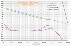
OP27 With Enhancer = 0.001% @ 1kHz
OP27 Without Enhancer = 0.003% @ 1kHz
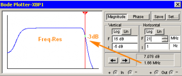
Interestingly with a much higher bandwith OpAmp the distortion is a LOT worse, & the bandwith is about 10 times less ? No other components were changed, or Anything else !
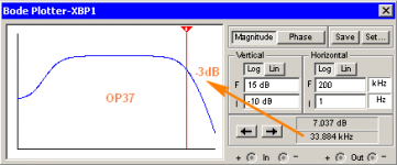
OP37 With Enhancer = 0.159% @ 1kHz
OP37 Without Enhancer = 0.049% @ 1kHz
I've been tinkering for a number of weeks with an "Enhancer" circuit added to an Amp, which improves both the THD & Loop Gain specs. I'd be interested in hearing your comments & suggestions etc, for where it "might" be improved etc.
Harry Dymond has been kind enough to assist me in various ways
& by simulating the circuit & establishing that it improves the Loop Gain. He also provided me with several links http://www.analog.com/static/imported-files/application_notes/AN-107.pdf I also observed greater bandwith with my Enhancer circuit, as in AN-107.
Figure 1 in AN-107
That arrangement seems different to mine.
Figure 3 in AN-107 - SOC = Gain peaking.
I noticed that in my bode plots too, i was able to reduce/flatten the peaking by juggling the values of the capacitors in parallel with the feedback resistors.
http://www.diyaudio.com/forums/solid-state/238252-odnf-no-gnfb-power-amp.html I hadn't looked at it until yesterday. There do "appear" to be similar things going on, but i don't understand it all !
Looking at my circuit -
OP27 With Enhancer = 0.001% @ 1kHz
OP27 Without Enhancer = 0.003% @ 1kHz
Interestingly with a much higher bandwith OpAmp the distortion is a LOT worse, & the bandwith is about 10 times less ? No other components were changed, or Anything else !
OP37 With Enhancer = 0.159% @ 1kHz
OP37 Without Enhancer = 0.049% @ 1kHz
Attachments
Interestingly with a much higher bandwith OpAmp the distortion is a LOT worse, & the bandwith is about 10 times less ? No other components were changed, or Anything else !
In my circuit it is all the same, lm6181 and lf411
. At least simulations shows that. I made circuit with lf411 and still can not believe how it sounds. Few days after without change, but I have to try with better op amp for experiment. It is audio band we are interest for, not ultrasonic.10 dB? - why bother - I show some composite op amps circuits with lots more audio band added gain:
http://www.diyaudio.com/forums/solid-state/45794-high-loop-gain-composite-op-amp-circuits.html
the 1st few manage lots of added gain inside the global loop
post #10 shows a sim of Harlod Black's 1st feed forward error correction method, in the "current dumping" form, applied to one Bob Cordell's example amps with slow output Q
I would worry about one of your schematics - not near enough current gain to drive 8 Ohm nominal loudspeaker load - added voltage gain can't help there
Last edited:
I see a lot of proposals to reduce THD - some are quite complex (Stochino is one example) and Walkers current dumping another, requiring some closely attached components. I've put my bets on what I call AFEC. It was pointed out a few weeks ago, Hitachi used a similar scheme about 25 years ago but I never took off for some reason. AFEC offers about 20 dB of distortion reduction at 20 kHz, and you get DC servo offset reduction as a by product. Most importantly, it's really simple!
Augmented Feedback Error Correction (AFEC)
Augmented Feedback Error Correction (AFEC)
Bonsai;3544209 I've put my bets on what I call AFEC. [/QUOTE said:Me too.
[Off topic]
There are some possible small developments that could be used. Eg. peaking on square waves could be reduced by adding a small cap across the feedback resistor and maybe making use of an op amp with a shut down pin to switch the AFEC off during clipping via an opto used as a baker clamp instead of a diode.
[/Off topic]
Some good ideas there! I will need to try them out.
One thing, if you use an opamp with a shut down pin, the turn on and turn off need to be very fast and clean. Another option here is to simply reduce the AFEC gain during clipping. This could be acheived for example, by shunting the AFEC feedback loop with a low value resistor - again, response time in order to avoid any funny artifacts is the key. If you are building anything, I's be interested to see your results. I am some months away from my new power amp (CFA 400 Watts) but that will incorporate AFEC which I will be able to switch in and out.
One thing, if you use an opamp with a shut down pin, the turn on and turn off need to be very fast and clean. Another option here is to simply reduce the AFEC gain during clipping. This could be acheived for example, by shunting the AFEC feedback loop with a low value resistor - again, response time in order to avoid any funny artifacts is the key. If you are building anything, I's be interested to see your results. I am some months away from my new power amp (CFA 400 Watts) but that will incorporate AFEC which I will be able to switch in and out.
Last edited:
Originally Posted by overall feedback
It is audio band we are interest for, not ultrasonic
Sure, but having a high internal bandwith with very low THD, is a good starting point.
@ mcd99uk
Thanks
Originally Posted by jcx
10 dB? - why bother
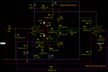
Well that's just for starters. The circuit i've shown is one that sims & works as described.
The 8.2 Ohm load was just there as one option. With for eg 32 Ohms, THD @ 1kHz is unmeasurable.
But it's NOT really about this Amp, it's about the Enhancer circuit which could be configured to work with other Amps & PreAmps etc. The components around U2 & connected to U1, are only provisional. The main purpose is for people to experiment with other values, & sim it themselves, to discover what's possible etc, & post their results
I'll take a look at the link, thanks.
@ Bonsai
No doubt your AFEC is another valuable contribution in the grand scheme of things, & i wish you All the best with it My design is still in it's early stages, & isn't perfected yet. Hopefully with input from others who are more skilled in the art, it "might" be
***************
I've realised why the OP37 THD result was so poor. I forgot it requires a gain of 5 or more. Changing it improves things substantially.
U1 = OP37 & U2 = OP27 - C4 = 33pf & C8 = 10pf
THD @ 1kHz = 0.001% or less
The bandwith looks pretty good to me, & that's with those output trannies !
Attachments
Er, what exactly is the difference between Zero D's circuit and AFEC? It's exactly the same principle as far as I can see.
Bonsai, I've had a very brief look at your AFEC document (as always, thank you for documenting your work so thoroughly and sharing it freely) and I don't trust your loop gain simulation. You should see a difference between AFEC on and AFEC off. The circuit is not feed-forward, so where is exactly is the improvement in THD coming from if not by an increase in loop gain?
Is figure 5 the circuit you used for loop gain simulation? The output of the AFEC circuit (after R74) is labelled "Vfb", but I can't see any other node in the circuit labelled similarly, so where is the AFEC signal going?
Bonsai, I've had a very brief look at your AFEC document (as always, thank you for documenting your work so thoroughly and sharing it freely
) and I don't trust your loop gain simulation. You should see a difference between AFEC on and AFEC off. The circuit is not feed-forward, so where is exactly is the improvement in THD coming from if not by an increase in loop gain?Is figure 5 the circuit you used for loop gain simulation? The output of the AFEC circuit (after R74) is labelled "Vfb", but I can't see any other node in the circuit labelled similarly, so where is the AFEC signal going?
Harry Its not feed forward - as I note in the document, it augments the normal feedback loop, so yes, it does work by increasing loop gain, but not by brute force. Most of the error correction (read: distortion reduction) in a normal amp is provided by the main loop. Any residual error (distortion) can be seen as the main loop simply running out of steam. AFEC corrects for that by comparing the output signal with the input and injecting an error correction signal into the feedback node. This is in marked contrast to feed forward schemes, or approaches that accomplish low distortion through very high loop gain.
As I noted in my write up, some more work is required to flesh out the design. Your comments about the loop gain plots are acknowleged - thanks for that input (hell, its difficult to avoid a pun here, no matter what I write!).
Maybe you'd like to take a bash at the loop gain equations which would help to formalize the approach.
Last edited:
The following is applicable to both Power Amps & OpAmps.
I've been tinkering for a number of weeks with an "Enhancer" circuit added to an Amp, which improves both the THD & Loop Gain specs. I'd be interested in hearing your comments & suggestions etc, for where it "might" be improved etc.
Harry Dymond has been kind enough to assist me in various ways
I also observed greater bandwith with my Enhancer circuit, as in AN-107.
Figure 1 in AN-107
That arrangement seems different to mine.
Figure 3 in AN-107 - SOC = Gain peaking.
I noticed that in my bode plots too, i was able to reduce/flatten the peaking by juggling the values of the capacitors in parallel with the feedback resistors.
http://www.diyaudio.com/forums/solid-state/238252-odnf-no-gnfb-power-amp.html I hadn't looked at it until yesterday. There do "appear" to be similar things going on, but i don't understand it all !
Looking at my circuit -
OP27 With Enhancer = 0.001% @ 1kHz
OP27 Without Enhancer = 0.003% @ 1kHz
Interestingly with a much higher bandwith OpAmp the distortion is a LOT worse, & the bandwith is about 10 times less ? No other components were changed, or Anything else !
OP37 With Enhancer = 0.159% @ 1kHz
OP37 Without Enhancer = 0.049% @ 1kHz
I'd bandwidth limit the signal to your enhancer Zero D. This is easy, since in practice in means you just take the reference signal after the amplifiers input filter.
Some good ideas there! I will need to try them out.
One thing, if you use an opamp with a shut down pin, the turn on and turn off need to be very fast and clean. Another option here is to simply reduce the AFEC gain during clipping. This could be acheived for example, by shunting the AFEC feedback loop with a low value resistor - again, response time in order to avoid any funny artifacts is the key. If you are building anything, I's be interested to see your results. I am some months away from my new power amp (CFA 400 Watts) but that will incorporate AFEC which I will be able to switch in and out.
On that time scale I should reach prototype stage on my CFB amp (simulating at 380W into 8R, wonder what reality will be
) before you. I reckon I'm about a month away.Then I plan on experimenting with different ideas with the AFEC. One of them being using a CFB op amp. I believe there's a lot of potential in the AFEC idea.Yes, you right response time and switch on characteristics are important. You would need some sort of time delay at least before switch on.
Just been wondering could both schemes be used together?
Last edited:
You should make AFEC switchable- at least then you can compare, but also easily switch it out if you have problems initially. You will want to get the amp working perfectly first without AFEC running.
Sound advice, been thinking about the switching, my donor amp chassis has two switches on the back and three front panel LEDs. One switch and LED could be the AFEC
The other switch was always going to be one for switching the amp from normal mode to active (with internal electronic crossovers)It would be a good idea to do the maths of AFEC and how it interacts with the amp. I keep wondering whether there is an alternative setup approach where the amp and AFEC can be matched together rather than treating the AFEC as a bolt on extra. I have been messing with this approach in simulation, but with no mathematical basis. It seems you can wind the AFEC right up and still have a stable amp with good clean square waves and of course very low THD. This is all circumstantial with no hard evidence or science to back it up.
You need to start off with a well compensated amplifier - so, no ringing or overshoot, plenty of phase margin - I'd say minimum of 45 degrees ( I usually go fo 60 degrees). Then you switch AFEC in, tapping its input after the input bandwidth filter. If you do this, and I highly recommend it, you will need to buffer the input signal.
AFEC feedback resistors need to accurately match the main amplifier feedback resistors - should be easy enough to do.
After this, switch in AFC and then adjust the value of the comp cap that encloses the AFEC control amplifier to get the best small signal square wave response - again, no overshoot or ringing
Once this is done, check the behavior under clipping conditions. The diode clamping network around the main AFEC error correction amp is important to aid recovery.
Yes, in the simulator you can wind AFEC right up and get away with it. but in practice I doubt it would work - I'll have to do some more work in the simulator on this. I suspect you can also see this whole AFEC thing as the AFEC control amp being the main signal amp, helped along by the power amp, and not the way it is now. In that case, the comp might be a bit different, but I need to think about it a bit more. I don't think the simulator evidence is circumstantial BTW - after all, the results rest on firm well understood math, and if not always reflecting reality, it's how the tool is applied, and not the tool itself. I also want to look into its application in an inverting configuration amplifier, since there is the potential to obviate common mode distortion.
I'd the most important 1st step is to start off with a stable amplifier - if you don't, you will be chasing your tail.
Last edited:
All good advice. This roughly how I've been doing things. The AFEC feedback resistors are an exact copy. Small signal response is where I have been going wrong though. I've been doing it on large signal square waves.
Stability of the base amp and production of square waves has been a priority. Keantoken suggested looking at the group delay. Get good group delay and you'll get good square waves. This is exactly what has happened. Simulated PM = 82 degrees and GM = 12dB.
I like to experiment, try things out. It's just occurred to me that you could set up the AFEC while looking at the group delay?? Get a setup that doesn't affect group delay and the square waves will be good.
I like a more global view - it looks like the circuits in play are conventional negative feedback - you just need to have an educated view of the conditions, definitions of "conventional negative feeedback" - and its equivalents, and sometimes the linear signal feedforward "2nd" degree of freedom...
and the work refernced in the final para of the page above:
...
http://www.control.lth.se/~kja/modeluncertainty.pdf
From K J Astrom “Model Uncertainty and Robust Control”
“fair use” excerpt:
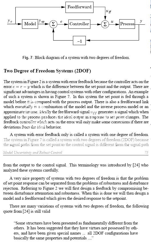
Be sure to read that last para!
and the work refernced in the final para of the page above:
The counterargument:
Hawksford/Cordell error correction is a 2 degree of freedom linear feedback control system,
All expressions of 2 degree of freedom control systems are equivalent.
Therefore Hawksford/Cordell error correction is equivalent to conventional error feedback with a command prefilter
Therefore the output linearizing disturbance rejection effect is exactly equivalent to error feedback and has the same gain-bandwidth/stability limits of ordinary 1 degree of freedom error feedback
A little reading: (slow to load, ~ 500K )
[I've referenced this a few time before in this thread I.M. Horowitz, "Synthesis of Feedback Systems" 1963 - that mkes this a 40+ year old "controversy"]
I like Bob's circuit, I do think understanding it as a local feedback loop and tailoring its loop gain and frequency response is likely to be a good way forward
Last edited:
Thanks for sharing jcx - I'll have to plough through those papers when I have some time.
I agree AFEC uses conventional feedback networks, and its not feedforward.
The error using conventional feedback is assymptotic, the difference between the 0 error value and the actual value being a function of, amongst other things the loop gain. AFEC IMV simply allows the error gap to be closed to a substantially smaller value with a second feedback loop. As I noted earlier, a more conventional approach would be to simply raise the main loop gain - something your composite solution does.
Regards
BTW, the link http://www.control.lth.se/~kja/modeluncertainty.pdf
seems to be broken - can you re-post it?
seems to be broken - can you re-post it?
- Status
- This old topic is closed. If you want to reopen this topic, contact a moderator using the "Report Post" button.
- Home
- Amplifiers
- Solid State
- THD & Loop Gain Enhancer