I must see the schematic diagrams to understand, what you mean.Hi tief,
I am using two independent stage(Voltage Follower for output stage) in single global FB (current sense). I cannot reach many advantage from single stage like commonly used.
Perhaps two voltage gain stages + power buffer against one voltage stage + power buffer - both with single NFB loop?
that's what i figured....
btw, don't know if anyone's mentioned it yet, but Yamaha made an amp with an impedance control, and they weren't the first. Electro-Voice made a "circlotron" amp that had an impedance control that varied the ratio between voltage feedback and current feedback, and that was back in the 1950's.. the idea has been around for quite a while, and it's not difficult to implement. the end user, however needs to have some understanding of what it's for and when and how to use it. otherwise it's just a complaint generator or in some cases an accident waiting to happen. for those who do know what it's for, unless they use a lot of different speaker systems on a constant basis, it will be a "set and forget" function, and once they have it where they want it, will want it out of the reach of other people's fingers.
btw, don't know if anyone's mentioned it yet, but Yamaha made an amp with an impedance control, and they weren't the first. Electro-Voice made a "circlotron" amp that had an impedance control that varied the ratio between voltage feedback and current feedback, and that was back in the 1950's.. the idea has been around for quite a while, and it's not difficult to implement. the end user, however needs to have some understanding of what it's for and when and how to use it. otherwise it's just a complaint generator or in some cases an accident waiting to happen. for those who do know what it's for, unless they use a lot of different speaker systems on a constant basis, it will be a "set and forget" function, and once they have it where they want it, will want it out of the reach of other people's fingers.
That reduces my surprise at so far not seeing amplifiers with impedance controls; it is simple and I expect it to have been done in the past just out of probability.
The impedance knob is pretty much a set-and-leave thing but having the ability to set and leave is what I think is useful about it. At least you have the ability to set it.
With my kit the builder would be able to put the knob wherever he/she chose. It could be a big wooden knob on the front of the amp or a lockable trim-pot hidden behind a cover; whatever you like.
I find I leave my impedance knob alone with my particular set of speakers but when trying other sets out (which during the DIY fest we have each year happens a lot!) it's great to dial the damping around to what suits a given speaker system and room better. Some people of course just prefer an over or under damped sound too.
No, not inductive or capacitive mis behave. I am familiar with this disgusting sound. Probably it caused by amplifier that still have part of low output impedance at high output impedance operation. The effect is it disturb our ears natural compressing sense (wrong sensing than oscillating or something). We have automatic dynamic compressing system in our ears that adjust its sensitivity itself.
And yes, I create another amplifier with already low output impedance at its voltage follower and no interesting sound at it.
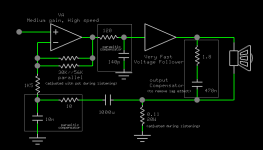
This schematic is my last adjustment, There still compensator added at the output that should be removed when this lag problem is solved.
And yes, I create another amplifier with already low output impedance at its voltage follower and no interesting sound at it.
This schematic is my last adjustment, There still compensator added at the output that should be removed when this lag problem is solved.
Attachments
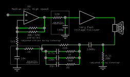
Hi, tief this my last schemetic, now without output compensator.
Hi unclejed,
1950's?, I feel that something missing in this Voltage and Current feedback technique, although this technique could produce very good sounding. I am now starting simulating power gain to revive my power source project. With power source driving, the loudspeaker nonlinearity, speaker function as big microphone and spring effect and many other may slightly reduced. The only problem is loudspeaker bad efficiency. But I am not sure which power source to choose, tubes or charged inductor (forward converter).
Hi DUO,
Can you post your amplifier topology? or which topology you follow?
Attachments
Last edited:
As I have explained, my amplifier simply takes the sum of voltage and current derived feedback nodes and uses this for its global negative feedback loop.
You can take more or less any high gain multi-stage topology that works with ordinary resistor-divider negative voltage feedback and modify it to work like I have; the desired effect is essentially the same in all cases and sounds the same from amplifier to amplifier. I have demonstrated this using chip-amps such as some of the common gainclone IC power amplifiers and also fully discrete topologies based on the three-stage lin concept and others. The effects are general and repeatable.
You can take more or less any high gain multi-stage topology that works with ordinary resistor-divider negative voltage feedback and modify it to work like I have; the desired effect is essentially the same in all cases and sounds the same from amplifier to amplifier. I have demonstrated this using chip-amps such as some of the common gainclone IC power amplifiers and also fully discrete topologies based on the three-stage lin concept and others. The effects are general and repeatable.
Now I understand, what you mean. Very special is for me the serial resistor (in your case 120 ohms) by your compensator network "parasitic compensator".Hi tief,
I am using two independent stage(Voltage Follower for output stage) in single global FB (current sense). I cannot reach many advantage from single stage like commonly used.
I must see the schematic diagrams to understand, what you mean.
Perhaps two voltage gain stages + power buffer against one voltage stage + power buffer - both with single NFB loop?
Hi, tief this my last schemetic, now without output compensator.
However - this is a good basic topology for creating an evaluation amplifier, because the possibility to compare various topologies both for voltage gain stage, current gain stage (power follower) and various topologies for the NFB loop. Also that mode, where the power follower isn't in the NFB loop, is easy to realize.
Last edited:
ahem... I would say that's not quite true. There is indeed no global voltage NFB loop, but there IS an overall ("global") current NFB loop!Also that mode, where the power follower isn't in the NFB loop
BTW:
For the record, a few years ago I too have experimented with "variable" (adjustable) impedance drive using mixed-mode NFB with a configuration which (likely) was similar to that used by Duo (using an LM3875 chip-amp based setup, you may find that here).
Unfortunately, overall my results have not been very satisfactory, 'cause for some reason my test amplifier was eating up a lot of music details no matter what output impedance was "dialed in" (even setting it such that it would not be really much different from a typical "gainclone"). I never really understood why this happened (maybe some "wrong" component used somewhere and/or a layout problem...
 ).
).Apart from this, the experiment have sort of confirmed that several (not all) "conventional" speakers do indeed like to be driven with a somewhat high-ish impedance, in the ballpark of a few ohms (that's about the typical output impedance of NFB-less tube amps...).
More recently, I am experimenting with another topology which may be also used for a variable Z-out amplifier. That's basically a power current mirror (with plenty of current gain):
www.audiofaidate.org - sand games 2: tu(be)mulator
I'm obtaining great results from this thing driven by an SE tube "front-end" (but you can use SS too... and putting some variable Z resistive network before the "SSOPT" you can easily use it as a variable output Z amplifier).
BTW, another somewhat related (and interesting) discussion is here:
The Secret of Tube Amplifiers Revealed - and much more!
(did anyone mentioned that thread already? can't remember, sorry).
Last edited:
Secret of tube amplifier revealed? It must be interesting.
I am going to make my power gain, the concept is, it gaining forward power x100 and divide reverse power /100.
5watt tube amp + power gain = 500W tube amp
5watt chip amp + power gain = 500W chip amp
5watt firstwatt + power gain = 500W firstwatt
etc.
Hi, DUO, you may try my configuration, it has good sound.
Hi, tief this is one example of voltage follower. I am going to use this one in my power gain project.
http://www.diyaudio.com/forums/ever...eally-i-post-some-proof-here.html#post2203189
unixman, the amp in your link looks like a simplified Howland current source. for a complete description of Howland current sources, NatSemi has an app note written by Bob Pease here:
http://www.national.com/an/AN/AN-1515.pdf
the "op amp" in a Howland current source can be ANY differential amp, including an audio power amp...
http://www.national.com/an/AN/AN-1515.pdf
the "op amp" in a Howland current source can be ANY differential amp, including an audio power amp...
Last edited:
Member
Joined 2009
Paid Member
unixman, the amp in your link looks like a simplified Howland current source. for a complete description of Howland current sources, NatSemi has an app note written by Bob Pease here:
http://www.national.com/an/AN/AN-1515.pdf
the "op amp" in a Howland current source can be ANY differential amp, including an audio power amp...
I see some similarities here...
SRPP+ All-in-One & Impedance Multiplier Circuits
well, yes, sort of. It can be seen that way. But there is a fundamental difference. A true HCP is a voltage to current converter: input impedance is fixed and output current is proportional to input voltage.unixman, the amp in your link looks like a simplified Howland current source.
In the circuit I have used, (*) output current is proportional to input current, not to input voltage. (both input & output voltages are basically "indifferent", as far as you do not exceed the circuit "compliance"). Thus it is a "current mirror" (with current gain). And of course its input impedance is all but fixed: instead, it rather "mirrors" the impedance of the load (times the current gain factor).
A similar result can be obtained also using a (proper) "improved HCP", as done by Mauro Penasa: http://www.diyaudio.com/forums/chip-amps/55925-lm3886-stasis-power-buffer.html
But "my" circuit is simpler, does not require critically matched resistors and (as far as the driving impedance is not too small) can use an LM3875/3886 without requiring any extra compensation for stability.
(*) N.B. - just to make it clear: although for convenience I gave a nick name to "my" circuit , I do not pretend to have invented anything! I've just applied an otherwise well known circuit to accomplish my goals.
sure. I thought I have said that already...the "op amp" in a Howland current source can be ANY differential amp, including an audio power amp...

yes, I too noticed that one.
Basically it's the same thing.Well Unixman, after the trials with the chipamp, perhaps we should have you for another starter here with Duo's working version of the adjustable impedance control.
It would be good to have a few folks get on board this project so that when he's ready (it seems there's plenty of time to save up the few dollars) we can all see what results are possible. This seems to me to be a great opportunity to try something worthwhile with our speakers - something we probably never thought would be easy to do. Maybe we could even get a bit of life out some of those DIY speakers in the garage we never really liked.
It's another topic but I wonder what useful measurement of a loudspeaker in its enclosure could be made with a device like this.
In view of the favourable comments about the amp, it seems it might be nice to have in the home when you're done with it. Thats better than just another pile of parts you have to recycle or scrap.
BTW: just to make it clear and to avoid possible mistakes: my "SSOPT" (what you call the "chipamp", I guess) in itself is NOT, by no means, a complete amp!Well Unixman, after the trials with the chipamp, perhaps we should have you for another starter here with Duo's working version of the adjustable impedance control.
I call it the "Solid State Output Transformer" for a reason: it behaves much like a transformer:
* It does NOT have any definite input impedance of its own. It "reflects" the load impedance * gain;
* It does NOT have any definite output impedance of its own. It "reflects" the front-end output impedance / gain.
like in a transformer, input and output currents are bound by a fixed ratio (gain).
Again like in a transformer, input and output voltages are bound by a fixed ratio (~= 1).
But, unlike in a transformer, the in/out voltage ratio is not the inverse of the in/out current ratio. In fact, in the "SSOPT" the output voltage "follows" (is almost equal to) the input voltage.
That is, unlike a real transformer which obviously can only have power losses, this thing may have plenty of power gain.
Nonetheless, it may conveniently be regarded as a (indeed very special...) transformer.
I had the idea to use such a circuit for driving a loudspeaker while trying to find a way to replace the (bulky & expensive) OPT in a tube amplifier with some SS circuit. But without making yet another "typical" hybrid amplifier. Which basically are nothing else than a tube preamp in front of an SS power amp (and sounds like such a combination, not like a tube amp). No way.
I wanted a "real" tube amp. Sounding like a real tube amp. Thus, among the other things I wanted something that did not "isolate" the tube amp from the load. Quite the contrary, I wanted only the "output" tube(s) to deal with the load. The SS circuit "in the middle" had not to mess with the load at all.
(yes, I do believe that quite much of the "tube sound" has to do with tube-load interactions, including but not limited to the relatively high output impedances they present to the load).
That is, I needed something that behaved just like an OPT... and there it come the "SSOPT".
Which happens to have a nice side-effect. Not only it does replace the OPT, it also render power tubes unnecessary!
In fact, given the high power gain easily obtainable, you can build a super-powerful SET using only a "small signal" tube in front of the "SSOPT". Nevertheless, it is still that small tube which drives (controls) the load. The "SSOPT" in the middle only acts just like the "power steering" system in your car.As said I actually built something like that. It's still only a prototype, but it works and -most importantly- sounds beautifully. Yes, like a very good, real SET. At a small fraction of the costs, weight, size, power consumptions...
Back on topic. To get a variable impedance amplifier, as I was suggesting in a previous post you could use an SS "front-end" (a low power amplifier capable of relatively high voltage swing) with a relatively low (and constant!) output impedance. I'd use a pure class A, NFB-less design for that purpose (perhaps one of Pass's nice designs adapted to the task?).
An appropriate adjustable resistive network connected between such a front end and an "SSOPT" can be used to set the impedance seen by the SSOPT input and thus the impedance seen by the load (output impedance).
Such network could be as simple as just a series (variable) resistor, but I'd try to design some "smarter" network such that the volume does not change too much with the impedance settings.
But sorry, I've no time to design and/or to try this out for you at this time. If you like the idea, you have to develop and try it out yourself.
I can only assure you that IMO/IME the simple LM3875-based "SSOPT" I've built is one of the most "transparent" piece of audio electronics I've ever heard. Some audio cables degrade the sound more that it does. If properly built, the sound you get out of it is mostly (if not only) determined by the front-end you connect before it. Being the "front-end" a low power, low current thing, it's cheap and easy to experiment and have a lot of fun with it. (BTW: I'd suggest you to also try using some tube there...
).
Last edited:
Member
Joined 2009
Paid Member
The consuming passion for tube sound replication is, I think, a much broader aim, and quite a different topic.
I've adopted the approach that aiming for 'tube sound' is really just about avoiding a harsh or unpleasant sound that some people associate with SS amps and actually has nothing to do with how tubes sound. It's also a fun excuse to go designing in some harmonic distortion which I quite like.
I think the idea of exploring designs that exploit some interaction with the load is another fun direction to explore, perfect for some DIY !
- Status
- This old topic is closed. If you want to reopen this topic, contact a moderator using the "Report Post" button.
- Home
- Amplifiers
- Solid State
- That curious extra knob, or: "Trans-Amp"