....I really do not see any special prerequisites, since there are almost no corrective capacitors in the circuit. But it seems that the entire NAIM system operates on the transmission accuracy in the "amplitude-time grid", and not in the "amplitude-frequency" one.
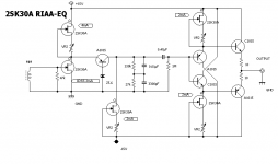
You will have Miller capacitance between the collector and base connections with Q1 and Q2.
Miller capacitance is proportionate to the area of the collector to base junction and inversely proportionate to the square root of the voltage applied to the collector.
For example the positive voltage at the collector of Q1 will be quite low due to the 22k collector load - this value being calculated to roll off the high frequencies without adding an external capacitor. For Q2 the voltage regard 0 volts as a negative supply source.
The MC33079 is good enough to chalenge both the Naim original and higher cost op amps. I agree with Mark that a modular design is not ideal even when the real Naim with gold plated edge connectors. DIL sockets are worth the risk. Final version can be without them.
The other fact with the 33079 is you could do a try out dead bug to get an idea if this idea will suit you. Then do the NAD style circuit on strip board as a try out. At first use a set of RCA sockets as a switch. If the sound degrades at the PCB stage at least you know why.
Dead bug often forces simplicity which very often sounds better. I use the little 1/8 watt and 1206 SMD resistors if so. My ground is a solid bar that also holds the design in the air. It's fun to take pen and paper to see how it will look. I think if the dead bug circuit is directly made as a PCB with similar layout is will sound almost as good. If SMD place them close to the chip. SMD 33079 costs about 50% the price of 1 cigarette in the UK! I guess that's shifting stock as they are worth at least 3 cigarettes. 4 devices for $0.40 US.
I really like the sound of 3 or more MC33079 sections as one op amp. The noise reduces to about 2 nV/root Hz and also sounds more pink. Theory says it will. It is called statistical noise reduction and works for actual statisitics. The generation of noise is random in the starting time which means a complex series of sine and cosine waves in a Fourier sequence is created. The other op amps by phase difference make for a small noise reduction be vector subtraction. Out of phase speakers reduce noise the same way. The Naim MC input used 5 transistors in parallel for the same reason. In theory the Naim MC should be very quiet. It isn't so could do with a redesign.
Member
Joined 2009
Paid Member
The MC33079 is good enough to chalenge both the Naim original and higher cost op amps. I agree with Mark that a modular design is not ideal even when the real Naim with gold plated edge connectors. DIL sockets are worth the risk. Final version can be without them.
The other fact with the 33079 is you could do a try out dead bug to get an idea if this idea will suit you. Then do the NAD style circuit on strip board as a try out. At first use a set of RCA sockets as a switch. If the sound degrades at the PCB stage at least you know why.
Dead bug often forces simplicity which very often sounds better. I use the little 1/8 watt and 1206 SMD resistors if so. My ground is a solid bar that also holds the design in the air. It's fun to take pen and paper to see how it will look. I think if the dead bug circuit is directly made as a PCB with similar layout is will sound almost as good. If SMD place them close to the chip. SMD 33079 costs about 50% the price of 1 cigarette in the UK! I guess that's shifting stock as they are worth at least 3 cigarettes. 4 devices for $0.40 US.
I really like the sound of 3 or more MC33079 sections as one op amp. The noise reduces to about 2 nV/root Hz and also sounds more pink. Theory says it will. It is called statistical noise reduction and works for actual statisitics. The generation of noise is random in the starting time which means a complex series of sine and cosine waves in a Fourier sequence is created. The other op amps by phase difference make for a small noise reduction be vector subtraction. Out of phase speakers reduce noise the same way. The Naim MC input used 5 transistors in parallel for the same reason. In theory the Naim MC should be very quiet. It isn't so could do with a redesign.
I agree with you about MC33079 having used the dual op.amp MC33078 in my DIY preamp built on small project boards well over 10 years ago.
I bought some later production samples a while ago and compared them with National Semiconductor LM833P shortly before the company was taken over by Texas Instruments.
The circuit representation of the latter device is equivalent to MC33078 http://www.ti.com/lit/ds/symlink/lm833.pdf.
While I have a fascination with discrete low level circuits a more compact layout results from using an integrated circuit which make it practical to buffer the inputs by at the point where the signal entry point at the back of the case. It would be convenient to use one dual op.amp per stereo input socket pair.
This cuts down on wiring and the signals will be at low impedance.
As far as vinyl sources are concerned I prefer a low gain series feedback stage followed by an inverting one to perform the RIAA correction - a scheme adopted in some Rotel and Mission Cyrus models and advocated by Linsley-Hood. I have a Technics unit that has low noise FET's in the RIAA stage and a Naim moving magnet Stageline as points of reference.
Today we have better low noise transistors than when JV designed his moving coil design.
The benefit of 5 parallel transistors is 1/root 5 degraded by the current sharing emitter resistors - a noise improvement of less than 50%.
Who knows how well a Naim pre-amp will go with modern transistors.
Member
Joined 2009
Paid Member
Would you buffer each input before the signals reach a switching relay, or would you use a single buffer after the relays (thus saving parts and space) ? - and why ?
IMO, the only thing to justify that is to set each input at different gain, so that you get same output level from any of the inputs. Considering the different recording levels, though, I'm not sure how relevant is that.
I know that the newer Quad preamps have that option as well as many of the expensive preamps from companies like Classe, Simaudio, T+A etc.
Member
Joined 2009
Paid Member
I have decided to go with the relay option for selecting inputs - I appreciate all the encouragement and advice from posters on this question. In terms of buffers, my thinking is to have one buffer after the input selection relays instead of individual buffers per input.
I'm still chewing over in my head the best way to deal with the so-called rats-nest of wiring that a flexible and modular approach seems to require.
I looked up the data sheet for the MC33079 and it looks very competent. However, we have have enough voltage available to make a very good (low distortion) discrete buffer, a simple Diamond Buffer in Class A would be no slouch, would require no feedback loop (no feedback compensation), needs no pull-down CCS to put it into Class A and may even be less hungry for pcb space than the MC33079 (which would need voltage drops from the main supply rails). Thoughts ?
Last edited:
I built a discrete unity gain buffer using a pair of complementary FETs and a pair of BJT's. The design was by Linsley-Hood who professed not to be able to distinguish between this and LF351/353 op.amps - this mainly on the grounds of simpler circuitry and had better phase linearity. It has been a while since I used the preamp where I installed this input buffer.
As far as a pull-down constant current source connected to the output is concerned the circuit representation for MC33078/79 shows the output NPN's are driven in split phase with a second NPN in parallel with the output NPN in the negative half circuit.
The second NPN collector is loaded with a constant current source and there is an alternative current path via a diode and resistor to the output. This stage operates in a form of single ended Class A.
To me the solution is one lacking a problem.
It would be good to be able to stack all components on a pcb backing onto the rear panel - with an extension shaft for a volume control and one of those rotary switches with a cable connection to a slide switch with equivalent pcb terminals at the opposite end. I am using one of these in my current pre-amp however I think one would be lucky to be able to source these today.
One thing you might do with relays is use double pole versions so as to have less resistance and a fail safe. Look very carefully at the uses to get the right silver alloy. Some say low level switching for signal or telecoms. Consider to have ground switching if willing to spend money like this. As far as I can see the ground can be common to save money. Also have a mute between switching to stop clicks and bangs. A mosfet with a satated gate would be nearly zero ohms activated and M ohms with zero bias. I would imagine a 1 second CT on the gate capacitor about right, could be shorter.
Try a MC33078 with two batteries ( 9 V and 2 x 1uF and 1 x 10 nF on the op amp power pins ) to set a standard for the buffer. Built Dead Bug it will not cost much. 5 Vrms will exceed the NAP140 ability to follow. Although 100% negative feedback it is a very direct signal path and very fast. It should sound very like a cable.
Try a MC33078 with two batteries ( 9 V and 2 x 1uF and 1 x 10 nF on the op amp power pins ) to set a standard for the buffer. Built Dead Bug it will not cost much. 5 Vrms will exceed the NAP140 ability to follow. Although 100% negative feedback it is a very direct signal path and very fast. It should sound very like a cable.
You can use better quality parts in a discrete circuit.Thoughts ?
Member
Joined 2009
Paid Member
Member
Joined 2009
Paid Member
It is an interesting idea. It functions as a LTP that is NPN PNP. Looking back to No53 it is subtly different if saying that example ( or not so if being strict ). The interestingh thing which I infer is the NPN/PNP curves work to a better result. I hope someone simulates this for us as it looks to be a winner. It also looks like something Naim would have liked. It dates back to the era also.
I just bough a 1 kHz Wien Bridge oscillator good to -127 dB distortion so it says ( need to change it to 10 kHz in addition ). I won't attempt to measure below - 70 dB. If this circuit can do this I would be happy.
I just bough a 1 kHz Wien Bridge oscillator good to -127 dB distortion so it says ( need to change it to 10 kHz in addition ). I won't attempt to measure below - 70 dB. If this circuit can do this I would be happy.
Op-amps are convenient but have many problems that cannot be overcome. Not least that every component is made of silicon. People go to effort to find the ideal, exotic capacitor dielectric and then use an op-amp in the signal path.
I love great sounding circuits. I see a pre-amp as an opportunity to be fanatically "pure": to make a simple, no FB circuit using exotic, hand-picked parts in nice colours and shapes. Much easier to do than in power amps: the voltage gain can be low, the output R can be high and you can make a very linear circuit with choice bipolars.

Today, I briefly looked up using tubes at low voltages, like below 30V, for a pre. It can be done! But linearity is tricky and transconductance is very poor. Would require some ingenuity.
I love great sounding circuits. I see a pre-amp as an opportunity to be fanatically "pure": to make a simple, no FB circuit using exotic, hand-picked parts in nice colours and shapes. Much easier to do than in power amps: the voltage gain can be low, the output R can be high and you can make a very linear circuit with choice bipolars.
Today, I briefly looked up using tubes at low voltages, like below 30V, for a pre. It can be done! But linearity is tricky and transconductance is very poor. Would require some ingenuity.
Member
Joined 2009
Paid Member
Nigel, you can think of the 'standard' LTP as a folded Rush Cascode.
Low voltage tubes - yes lots of options. I've looked at it in a fair bit of detail and there are several options I could include but the need to provide heater power from the 36V power rail is a wasteful prospect. I have a few candidate tubes in my collection including some Nuvistors. My plan is evolving and tubes are not high on the list but at least still on the list!
Low voltage tubes - yes lots of options. I've looked at it in a fair bit of detail and there are several options I could include but the need to provide heater power from the 36V power rail is a wasteful prospect. I have a few candidate tubes in my collection including some Nuvistors. My plan is evolving and tubes are not high on the list but at least still on the list!
You can use a voltage multiplier PSU with a capacitance multiplier ripple rejector if tubes. I find a MOS FET best for that. The anode load can be a MPSA92 CCS. No LED's for the cathode please. The Cascode looks intesteting. It is almsot the ideal pentode-triode hybid.
Don't get told valves are a box of crayons. They give high gain without needing extra negative feedback. If looked at very carefully they can be very low distortion. To use a transistor CCS is no Frankenstein circuit. The triode valve is an ideal voltage amplifier and the transistor CCS is an ideal current amplifier.
Most read Self, some read JLH. You should read Morgan Jones. He covers the ground like Self except one feels he really is wanting to teach us. Between Self and Ben Duncan I would say. Not quite JLH.
https://www.amazon.co.uk/Valve-Amplifiers-Morgan-Jones/dp/0750656948
Member
Joined 2009
Paid Member
in this project we have only a dc supply coming from the power amp, to make a doubler we need AC. We could place a doubler in the power amp chassis and bring across tjis supply too but it's more work. I like tubes but I don't think it warrants the extra complexity of HT if low voltage options can work too. As you say, CCD loads could be used if wanted.
- Status
- This old topic is closed. If you want to reopen this topic, contact a moderator using the "Report Post" button.
- Home
- Source & Line
- Analog Line Level
- TGMC - a modular control pre-amplifier