Finally got my TGM8 build restarted.
Not sure if anyone else had this issue... but just a warning for others:
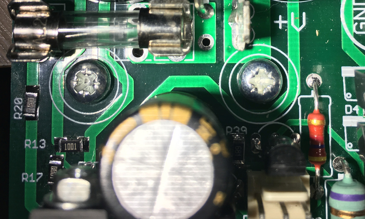
It is IMPERATIVE that you use an insulating washer on the pcb top side for the power transistor screws. Otherwise you could have the problem I had. In my case the screw shorted to the VBE multipler and shorted the node R13/R17 to the heatsink (you can see a bit of exposed copper on the track where this happened).
I guess I was lucky that it didn't short the rail(s) to heatsink, although my current limited bench supply would have prevented any pyrotechnics!
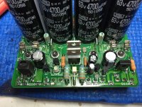
Ayway, the boards are more or less done now. Iq stablity is very good, offset stability (with temp) is decent. I'll do some AC and disstortion testing soon.
Not sure if anyone else had this issue... but just a warning for others:
It is IMPERATIVE that you use an insulating washer on the pcb top side for the power transistor screws. Otherwise you could have the problem I had. In my case the screw shorted to the VBE multipler and shorted the node R13/R17 to the heatsink (you can see a bit of exposed copper on the track where this happened).
I guess I was lucky that it didn't short the rail(s) to heatsink, although my current limited bench supply would have prevented any pyrotechnics!
Ayway, the boards are more or less done now. Iq stablity is very good, offset stability (with temp) is decent. I'll do some AC and disstortion testing soon.
Unwanted Bias
I'll cut to the chase. I went through the powerup sequence accordingly, and at about 20v rail, the bias was 48mv, but VR2 was already at minimum (0). Ran out of threads. I was able to zero the DC offset. At 28V, the bias was 100mV. The voltage across the sacrificial test resistor (100R over the fuse holders) was 10V or 100ma. Time to shut it down. I went through the usual checks of all components, proper value, proper orientation and tested the semis passively. I checked for shorts, and in particular from the power device mtg screws, as suggested on the recent post. Solder joints appear secure. No luck. BTW, I built 2 boards, and both have the same identical problem. (Redundant?...yes!) I now turn to you, gentleman, for assistance. I have not played music. If I do hook up speakers at 20V rails and it plays, I would be tempted to lower the bias by upping R13 to perhaps 2K. Probably not a good idea, since a problem is still lurking. Testing voltages would be of limit value for me without references. Any suggestions from anybody? I have not run across any thread that describes my problem, so am I a loner? If someone can deliver me relief, I will wave my wand against Mr Corona. Thank you, sirs.
I'll cut to the chase. I went through the powerup sequence accordingly, and at about 20v rail, the bias was 48mv, but VR2 was already at minimum (0). Ran out of threads. I was able to zero the DC offset. At 28V, the bias was 100mV. The voltage across the sacrificial test resistor (100R over the fuse holders) was 10V or 100ma. Time to shut it down. I went through the usual checks of all components, proper value, proper orientation and tested the semis passively. I checked for shorts, and in particular from the power device mtg screws, as suggested on the recent post. Solder joints appear secure. No luck. BTW, I built 2 boards, and both have the same identical problem. (Redundant?...yes!) I now turn to you, gentleman, for assistance. I have not played music. If I do hook up speakers at 20V rails and it plays, I would be tempted to lower the bias by upping R13 to perhaps 2K. Probably not a good idea, since a problem is still lurking. Testing voltages would be of limit value for me without references. Any suggestions from anybody? I have not run across any thread that describes my problem, so am I a loner? If someone can deliver me relief, I will wave my wand against Mr Corona. Thank you, sirs.
Unwanted Bias
I'll cut to the chase. I went through the powerup sequence accordingly, and at about 20v rail, the bias was 48mv, but VR2 was already at minimum (0). Ran out of threads. I was able to zero the DC offset. At 28V, the bias was 100mV. The voltage across the sacrificial test resistor (100R over the fuse holders) was 10V or 100ma. Time to shut it down. I went through the usual checks of all components, proper value, proper orientation and tested the semis passively. I checked for shorts, and in particular from the power device mtg screws, as suggested on the recent post. Solder joints appear secure. No luck. BTW, I built 2 boards, and both have the same identical problem. (Redundant?...yes!) I now turn to you, gentleman, for assistance. I have not played music. If I do hook up speakers at 20V rails and it plays, I would be tempted to lower the bias by upping R13 to perhaps 2K. Probably not a good idea, since a problem is still lurking. Testing voltages would be of limited value for me without references. Any suggestions from anybody? I have not run across any thread that describes my problem, so am I a loner? If someone can deliver me relief, I will wave my wand against Mr Corona. Thank you, sirs.
I'll cut to the chase. I went through the powerup sequence accordingly, and at about 20v rail, the bias was 48mv, but VR2 was already at minimum (0). Ran out of threads. I was able to zero the DC offset. At 28V, the bias was 100mV. The voltage across the sacrificial test resistor (100R over the fuse holders) was 10V or 100ma. Time to shut it down. I went through the usual checks of all components, proper value, proper orientation and tested the semis passively. I checked for shorts, and in particular from the power device mtg screws, as suggested on the recent post. Solder joints appear secure. No luck. BTW, I built 2 boards, and both have the same identical problem. (Redundant?...yes!) I now turn to you, gentleman, for assistance. I have not played music. If I do hook up speakers at 20V rails and it plays, I would be tempted to lower the bias by upping R13 to perhaps 2K. Probably not a good idea, since a problem is still lurking. Testing voltages would be of limited value for me without references. Any suggestions from anybody? I have not run across any thread that describes my problem, so am I a loner? If someone can deliver me relief, I will wave my wand against Mr Corona. Thank you, sirs.
Member
Joined 2009
Paid Member
Finally got my TGM8 build restarted.
Not sure if anyone else had this issue... but just a warning for others.
good note Dave!
It helps to use a small solid washer and hex bolt. Attached is what Do did back in post #776.
It’s a cramped pcb, because the overall size was limited by the free version of the layout software. If I were to re-do it today I’d get out my wallet instead of being a tight-wad and buy a software license!
Attachments
Last edited:
Member
Joined 2009
Paid Member
I'll cut to the chase. I went through the powerup sequence accordingly, and at about 20v rail.....
Hi there!
I think it’s a simple issue - you are using lower rail voltages than the baseline design. The adjustment range runs out of range using values intended for 36V to 50V rails. This means things may not be set up properly. If you want to stick with +/- 20V rails then a couple of resistor value changes should sort it out unless there’s another problem. I’ll need to check, using a Spice simulation, before I can give you the answer.
Last edited:
Member
Joined 2009
Paid Member
20V rails
If you are just testing with 20V rails, then you need to increase to 36V to 42V.
If you want to operate at 20V rails the you need to make some changes.
1/ The dc-offset relies on a -12V zener regulated voltage but at low voltage you are starving the zener of current and it will result in difficult-to-predict behaviour because the zener will be operating nearer it's 'knee'. Reduce R11 from 4k7 to 1k5 (or thereabouts)
2/ The VAS current will also be on the low side, reduce both R14 and R15 from 4k7 to 2k7
3/ The front-end will be lacking headroom from the +ve rail RC filter, reduce R18 from 560R to 220R (or thereabouts)
The dc-protection circuit will also not work at 20V if you've built it for 42V rails. For 20V rails you need to
4/ ensure the zener diode, D5, is at least a couple of volts below the rail voltage, even a 12V zener would suffice
5/ don't starve that zener, reduce R41 from 10k to 4k7
6/ don't starve the front end of the dc detect circuit, reduce R36 from 100k to 56k.
Unwanted Bias
Thanks Bigun for your prompt reply, as you always do. It is an indication of your dedication to the project and to your followers.
Allow me to clarify my problem. The power supply is rated at +/- 40V. I stopped at 28V during the setup, because the current draw across the 100R was too high at 0.1 amp. You stated previously it should be only tens of mA. I then increased the rails to 32V. Bias increased to 110mV. Bias adjustment was not able to lower the bias current, as it had bottomed out. I could have braved on and go to 40V, but I may be asking for trouble. The 100Rs were getting HOT! The better part of valor was to cry out for HELP. BTW, I did eliminate R8 and performed the other mods as suggested on post #1050.
As you can see, I am a newbee to this form and my ignoramus behavior is evident. I made changes to my original posts and did not delete them. Please feel free to wipe them out! Thanks.
Stan
Unwanted Bias
Many thanks, Dave. You hit the nail on the head, where previously I was striking my thumb! As you recommended, with R2 set at 2K upon powerup, the bias adjustment worked appropriately in the low end range. Voila! I am still in the process of checking out several other details before supplying it with music. If you can, kindly provide a moment to explain the reason why in this particular amp the bias pot needs to be at max before turning on for initial set up? It seems contra-intuitive and at variance with the procedure used to set up my other amps. Now I recall reading an earlier thread to adjust R2 'up' initially. Thanks for making it very clear that it should be at 2K.
Stan
Member
Joined 2009
Paid Member
Hi Stan,
The safest option is always to start at minimal bias current, there are shortcuts you can take but without delving into that what Dave suggests is good practice for ‘other’ amps too. It’s the approach I’ve taken too.
If you have the bias set appropriately and dc offset in a reasonable range, then there isn’t much left to do. You could leave the amp to ‘soak’, which means running on the bench for a few hours, preferably with enough bias to run warm. The idea of this is to flush out infant mortality problems with components and solder joints. You could, if you like, run some music into a dummy load and let it warm up a lot more. Then remove the signal and re-check bias and dc offset to see if you are still happy with them. Last but not least, if you have some unfortunate wire dress, where output and input are too close and create feedback oscillations, look for parasitic oscillations on a ‘scope. Remember to add an in-line air core inductor at the output - there’s much written about those on the forum.
Hope you’ve heard some music through the amp before nightfall!
If you can, kindly provide a moment to explain the reason why in this particular amp the bias pot needs to be at max before turning on for initial set up?
Stan
If you look at the schematic:
The voltage across VR2 is "regulated" by the Vbe of Q5... maximum resistance (2K) = minimum current in VR2 and hence R13.
The current through R13 (1K) determines the voltage across it.
The bias voltage is the voltage across R13 + VR2.
Amps with a CFP output stage need the bias voltage to be 2 Vbe's + the voltages across the "emitter" resistors. For the TGM8 that's the VBEs of Q6 + Q7 + the voltages across R30 and R31 (+ a tiny amount for the base resistors of Q6 and Q7).
This will happen when VR2 is a bit less than 1K.
If you set VR2 to zero all of the VAS current flows through R13. The VAS current varies with rail voltage (due to the bootstrap) so bias increases (dramatically!) with supply voltage... as you found!
Some designers add a resistor in series with VR2 to limit the maximum bias possible.
Gentleman, thank you for all your attempts to rectify my confusion. I am happy to report that I get it. Happily, I am not retardedly recalcitrant. My confusion stems from the observation that the bias pot was operating exactly the opposite when fired up at the minimum setting, as opposed to the maximum setting. That is, increasing the resistance, RAISED the bias. Lowering the resistance, DECREASED the bias, all opposite from the correct behavior which I have now achieved. So my actual question is why? Why did starting at the opposite extreme setting reverse the operation of the bias adjustment? I wonder if this phenomenon is unique to my amp, or has anyone else observed the same phenomenon? Perhaps, no one else has tried what I did. Now that the confusion is cleared (or clear), I believe that the proper procedure to set up an amp, including my prior builds is the same.
Many thanks again. This has been edifying.
Stan
Many thanks again. This has been edifying.
Stan
Member
Joined 2009
Paid Member
Hi Stan, I can’t say I’ve seen that particular behaviour. I know that sometimes the direction you have to rotate the pot might be different between amps depending on which way the pot was wired into the circuit i.e. pcb layout. One thing I’ve seen on a different amp is weird behaviour from a bias being adjusted was unstable bias and bias changes that weren’t consistent with the position of the pot - it was because the amplifier was oscillating, a sure fire way to have things behave strangely. I’m not saying that was the case with your build, but then again I haven’t played with all possible power rail voltages and other things and wiring and grounding can conspire to make things awkward if they are allowed! Anyhow, glad to hear it’s behaving now.
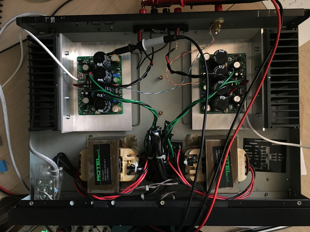
After a brief diversion to mend the power supply for my signal generator, I have now started testing the TGM8.
With my rail voltages I think the "helpers" are hindering!...
No load rail voltage is 40.9V.
With a 10R load I can see obvious clipping (and some hf oscillation on the positive peaks) at 20.7 VRMS. Which is about 29V pk @ 2.9A. The negative side clips at a bit higher voltage - which I suspect is due to the bootstrap current source.
20.7V RMS is 42W RMS into 10R.
With a 5R load I can see obvious clipping (and some hf oscillation on the positive peaks) at 17.7 VRMS. Which is about 25V pk @ 5A. The negative side clips at a bit higher voltage - which I suspect is due to the bootstrap current source.
17.7V RMS is 62W RMS into 5R. A bit feeble!
So where's all the rail efficiency being lost??
If we take the 5R case:
The 2SA1943 needs about 0.9V Vbe to do 5A. It also needs about 63mA of base current = 0.63V across R24.
So that means 1.5V across R20 which leads to 2.25V across R21.
At 5A the .33R resistor drops 1.65V.
Therefore we are losing about 5.5V (VCEsat of Q6 estimated at 0.1V).
My rail measurements were 33.3V on the + rail with about 1V of ripple at the conditions above. So at 25V peak we are losing about 8V... somewhat more than my calculation. I suspect this is due to the RMS measurements when converted to peak are in error due to the clipping.
I guess there is only about 2.25V more voltage swing available by removing the FETs and shorting R21. However I'm not convinced the FETs are doing much... with a gate voltage of 3.75V and a gate threshold (measured) of ~3.5V. I wonder if they are just starting to turn on at the peaks and are responsible for the oscillations?
My lowish supply rails and easy to drive speakers mean that the FETs are most likely redundant in my amp.
On a more positive note:
The amp is perfectly stable into all the capacitive loads I tried from 0.1u to 2.2u (even without parallel R)
Bias stability and output offset stability are fine.
Measured gain is 27.32.
Offset protection appears to work.
I've had it running at 10W into 10R for a while. Should be ready to listen soon
Last edited:
One thing I’ve seen on a different amp is weird behaviour from a bias being adjusted
I considered the same possibility of oscillation, Gareth. It makes sense and I will test it out. If this amp indeed is prone to oscillation, as Dave also suggests, what would you recommend as a remedy? Would change in the capacitive value of the Zobel network be worth considering?
Stan
I considered the same possibility of oscillation, Gareth. It makes sense and I will test it out. If this amp indeed is prone to oscillation, as Dave also suggests, what would you recommend as a remedy? Would change in the capacitive value of the Zobel network be worth considering?
Stan
Last edited:
Oscillation?
I will install the inductor, with confidence, realizing its benefits especially with your prompting, Gareth. Previously, I was ambivalent. This will be accomplished when the board is installed onto the chassis. I suspect that the placement outside the board is due to space limitation of the PCB. Would oscillation be better controlled if the inductor was closer to the board? If maximum RFI rejection is required, where is the ideal location..., at the beginning of the speaker cable or towards the end? Using a 10R - 20R parallel and in the lumen of the inductor will add a bit of additional inductuctance, probably inconsequential. As such, use of a carbon resistor is unlikely to be of any value, I suspect.
Stan
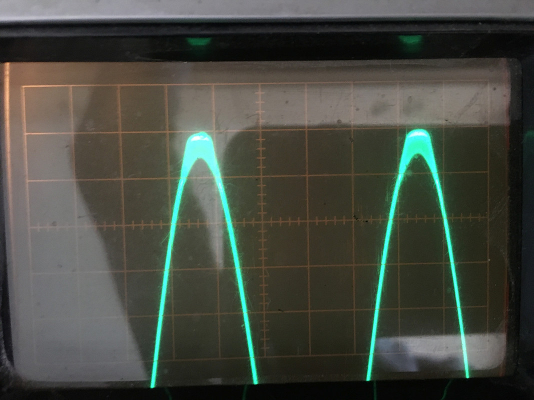
Just to be clear... the oscillation is only on the positive peaks of the sine wave at or near clipping. I don't consider this in any way dangerous to the speakers, especially in normal use. Apologies for my CrApple pictures, the oscillation looks blurred:
Had a listen for an hour this afternoon. Whilst trying not to suffer too much from honeymoon syndrome, it does sound very good!
Had a listen for an hour this afternoon. Whilst trying not to suffer too much from honeymoon syndrome, it does sound very good!
- Home
- Amplifiers
- Solid State
- TGM8 - my best amplifier, incredible bass, clear highs, no fatigue (inspired by Rod Elliot P3a)