Member
Joined 2009
Paid Member
Nice pic - Just to be sure, what amp are we looking at - these aren't my boards, did you make your own design ?
Do you have the output inductors right next to those huge input Clarity Caps - Is it possible you have some magnetic coupling from output to input caps right there in the chassis ? can you describe the wiring a little - where is the input to the amp ?
Do you have the output inductors right next to those huge input Clarity Caps - Is it possible you have some magnetic coupling from output to input caps right there in the chassis ? can you describe the wiring a little - where is the input to the amp ?
Last edited:
Member
Joined 2009
Paid Member
Here you are
RCruz, is this layout yours? Is it available?
I would like to try a non-SMD version, with a single-sided board.
Thank you.
Member
Joined 2009
Paid Member
non-SMD and single-sided would be really pushing it I think but sounds like an interesting challenge - from a commercial standpoint though, low cost double sided boards from China are the only sensible choice - for some people it could be cheaper than DIY boards. The parts cost for this amplifier is fairly high, it doesn't make sense to scrimp on the board.
One reason I use SMD is the parts are really easy to use - yes, easy, no leads to bend etc. I use large enough parts that they aren't a problem. Less solder too. And layout of SMD allows optimal performance.
If I were to layout a non-SMD version, double sided mind, I would want to make the board larger. And my free license for Eaglesoft doesn't allow me to go larger.
Last edited:
I think you may have an issue with the input caps and output inductors being too close together.
Thank you Bigun
So the proximity of the output inductors and input caps might be able to sustain oscilation as some sort of feedback ?
Once the oscillation is triggered I must turn off the amp and restart.... Do you believe it does have nothing to do with output laterals oscillation ?
RCruz, is this layout yours? Is it available?
I would like to try a non-SMD version, with a single-sided board.
Thank you.
Yes it is my layout heavily inspired by the original Bigun design but using laterals on the output.
It sounds big but with really sweet trebble.
Let me figure out how to tame the oscillatory tendency and I might be able to provide you two boards
")
Yes it is my layout heavily inspired by the original Bigun design but using laterals on the output.
It sounds big but with really sweet trebble.
Let me figure out how to tame the oscillatory tendency and I might be able to provide you two boards
TYVM! Good luck.
Member
Joined 2009
Paid Member
So the proximity of the output inductors and input caps might be able to sustain oscilation as some sort of feedback ?
I believe it's a strong possibility but if it is feedback amongst the wiring like that it should easy to check - just pull things outside the chassis, lay them out and move them around on the bench-top and see if simply re-orienting and pushing parts further away from each other could help. Those giant caps could also be microphonic - that's a conjecture only as I've no experience of using such giant caps.
Once the oscillation is triggered I must turn off the amp and restart.... Do you believe it does have nothing to do with output laterals oscillation ?
I've never used lateals, but my experience with MOSFETs is that they love to oscillate. They are extremely high speed devices. Even the parasitics associated with their packages and lead-wires can be enough to set them off. But when the do oscillate, it's usually in the vhf region, you'd only get an audible result through some additional mixing / non-linearity. This is why I suspect it's not the Laterals. I've been wrong before, many times.
Haven't had a chance to fix the defective speaker protection on the second channel that stays on no matter what. After this is done, hopefully soon, I'll be able to listen on my ATS-4 speakers. I might need your help to troubleshoot the protection circuit. What I want to do is set a high offset where the LED turns red and then would like to know what you suggest measuring while in this mode so we can determine where the issue is.
Thanks
Do
Thanks
Do
Member
Joined 2009
Paid Member
Member
Joined 2009
Paid Member
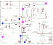
I've attached the circuit schematic for the part we're interested in.
I've marked with pink circles some nodes you could measure voltages at, the blue and pink circles too but they are on high impedance nodes so you need a high impedance voltmeter or 'scope - most modern instruments will suffice.
First off, I would double check - compare the circuit with your pcb so you can see that everything is in it's proper place. Compare with the other channel. Maybe measure the values of the resistors - although they are in-circuit you can get a rough idea in most cases if something is vastly wrong.
Attachments
Member
Joined 2009
Paid Member
In this circuit, Q17 is a switch. It turns on once there is a higher enough voltage on it's emitter - the current flow out through the base go ground goes through a zener diode. If the power rails are too low then the voltage across this zener will be too low to turn it on and Q17 remains off. In practice, it serves to cut-off power to the circuit when the power rails collapse. This means that when you hit the main off switch on the amp, the power rail voltages collapse and when they get below a set point Q17 turns off and cuts off the speaker so you don't hear any strange noises that some amps make when they power down. For the purpose of disconnecting the speaker in the case of dc voltage error on the speaker output - Q17 has no role to play.
Member
Joined 2009
Paid Member
The heart of the circuit is Q15. It switches the current on/off to the Opto isolator. The opto isolator provides the gate drive to the FETs and allows their Source connections to float up and down with the signal. If Q15 is on then the Opto should be providing a gate drive signal to the FETs which will appear as a voltage across R37. If this signal is present the speaker should be connected.
Q15 is has a base pull-up resistor R36 which biasses it in the normally 'on' mode. The voltage at the base of Q15 is established on power-up but not instantly. The current flowing through R36 first charges up C20. This provides a short delay before Q15 turns on and hence the speakers are not connected for a short time - just enough for the amplifier operating points to settle down and thus avoid any turn on noises through the speakers.
Q15 is has a base pull-up resistor R36 which biasses it in the normally 'on' mode. The voltage at the base of Q15 is established on power-up but not instantly. The current flowing through R36 first charges up C20. This provides a short delay before Q15 turns on and hence the speakers are not connected for a short time - just enough for the amplifier operating points to settle down and thus avoid any turn on noises through the speakers.
Member
Joined 2009
Paid Member
The fault detecting components are Q12 and Q13 and their associated passives.
R32 samples the amplifier output and together with C16 forms a low-pass filter so that the circuit is sampling the average dc-level and not the music signal. When the dc-offset is close to zero there will be zero signal at the junction of R32/C16. This means no voltage at the base-emitter junction of Q12 so it stays off; it also means no voltage at the emitter-base junction of Q13 so it stays off too.
And the speaker remains connected to the amplifier and everyone is happy. Unless you're playing Country music that is.
- Home
- Amplifiers
- Solid State
- TGM8 - my best amplifier, incredible bass, clear highs, no fatigue (inspired by Rod Elliot P3a)