Member
Joined 2009
Paid Member
My signal generator goes up to MHz but it's not as clean as the test point on my o'scope. When I do square wave testing I'm looking for mis-behaviour of the edges and 1kHz does fine. Higher frequencies only serve to increase power dissipation and have no other value. Everything you want to know from the square wave test is available at 1kHz; of course, to see detail you need to zoom-in on the edges (I can pull out the time-base knob for 10x).
Where I'm cautious is driving square waves into simulated speaker loads with capacitance. You need some load capacitance to see how your amp will behave with difficult loads, nasty speaker cables etc. You don't want to exceed the output SOAR of the power transistors by going rail-to-rail at 20kHz into such a load. I remember Rod Elliot explaining that when he tried to do this he didn't have enough time to adjust the trace on his oscilloscope before the power devices let out the magic smoke !
Where I'm cautious is driving square waves into simulated speaker loads with capacitance. You need some load capacitance to see how your amp will behave with difficult loads, nasty speaker cables etc. You don't want to exceed the output SOAR of the power transistors by going rail-to-rail at 20kHz into such a load. I remember Rod Elliot explaining that when he tried to do this he didn't have enough time to adjust the trace on his oscilloscope before the power devices let out the magic smoke !
Mark,
Why this comment? Bigun was not talking about Pass here, just explaining his point of view of how he test his equipment. We both know that we won't teach an old dog new tricks (talking about Papa). I'm guessing he pushes really hard to ensure high stability in extreme conditions?
Anyways this square wave thing is all because of me mentioning it in the first place for my tests. I'll try an octagonal curve instead! LOL
Have a good day!
Do
Mark,
Why this comment? Bigun was not talking about Pass here, just explaining his point of view of how he test his equipment. We both know that we won't teach an old dog new tricks (talking about Papa). I'm guessing he pushes really hard to ensure high stability in extreme conditions?
It is not about Pass but his test method, and it is not about high stability in extreme operating conditions.
The need is to think about stability at frequencies where these are in decline which happens at a rate more gradual than the attendant changes in phase.
This is a natural effect which can be compensated for in the circuit. There is a trade-off between low distortion at high frequency and decent stability so there is a need to get this right through testing.
Look at the output wave form of an amplifier with a 1 kHz square wave input either on a scope or in a simulation and work out the rise time of the vertical step from peak to peak. Then work out how many cycles per second this equates to.
When you have done that consider that stability issues arise in the MHz vicinity - you need to look for this in the right sphere.
Member
Joined 2009
Paid Member
Member
Joined 2009
Paid Member
Anyways this square wave thing is all because of me mentioning it in the first place for my tests. I'll try an octagonal curve instead! LOL
Have a good day!
Do
How’s that Octagonal coming along ?
")
Looking at the scope, a square wave test doesn't reveal anything more running 100kHz through the amp than does let say 100Hz.
Set the scope to 1uS/div and run 100Hz, look at the leading and lagging edges, now bump up to 100kHz, the edges will very probably look the same with all its eventual ringing or whatever might appear on the envelope.
The one inspection vast majority are missing to look at when using square wave test is the current cross conduction behavior of the OPS, for such inspection a non intrusive current probe is needed, or alternatively a differential probe hooked over E/S resistors, if such R's are used.
One can try use an ordinary voltage probe, but the oscilloscope needs to be isolated from the mains supply by a full transformer because the probe GND is connected to the mains GND through the chassis, then there's still a risk hooking up an ordinary voltage probe because of introduced stray capacitance's and inductances may alter the amplifiers behavior and even causing it to oscillate, in order to minimize any spurious effects one can try using starting with a 100Ohm in series with probe GND and another 100Ohm in series with the probe tip.
However, an exception are the common E/S OPS with resistors connects to the rails, in such case the above mentioned use of ordinary voltage probe is ok, series resistor with probe GND isn't needed when connected to the rails voltage, but the probe tip wouldn't hurt from using a 100Ohm (up to max ~1kOhm) series resistor.
The series resistor with the probe tip is a good practice also for other types of measurements in order to minimize the probe causing a circuit to alter its behavior.
As others have mentioned, 1kHz is a round and sound figure that works very well, higher frequencies is in most cases a hyperbolic demonstration worth next to nothing, power/heat stress can be equally well performed with sine wave.
Final note, cross conduction power dissipation using square wave versus power dissipation using sine wave are quite different things when testing the limits of the amplifier, don't confuse and mix up these two.
Last edited:
That’s what I figure, the nice thing about testing with a 1kHz square wave is not needing to test with MHz sine waves. But you want a steep rise time on your square wave, a good quality clean source.
I note that Rod Elliott has a section on square wave testing on his pages and one of his designs influenced your efforts here.
Elliott used 1kHz square waves in his tests however he gave two references for further reading - see the second one re 10 KHz testing.
http://frank.pocnet.net/other/AWV_Radiotronics/Radiotronics_1955/1955_06_AWV_Radiotronics_20_06.pdf
Linsley-Hood is another designer who subjected his designs to 10kHz square wave tests - including parallel capacitors.
Member
Joined 2009
Paid Member
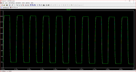
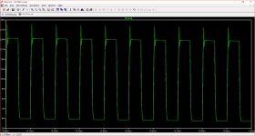
These are simulations.This is the output of an amplifier with a complementary bipolar output stage on square wave into 8R showing the overlaid results with parallel capacitor values of 5n,10n,100n,220n,470n,1u, and 2u in one shot.
In the real world you can ended up as picture in post #829(when using 1 or 2uf//8R) only with an overcompensated amplifier.
Are you sure that you like such an amplifier?
Last edited:
These are simulations.
In the real world you can ended up as picture in post #829(when using 1 or 2uf//8R) only with an overcompensated amplifier.
Are you sure that you like such an amplifier?
The point being made was not about the particular amplifier but the use of 10 kHz square waves to test for feedback loop stability.
The rise time of the step for a test frequency of 1kHz does not equate to a frequency in the domain where stability becomes an issue.
If one has electrostatic loudspeakers - difficult loads - but nonetheless reputedly having less distortion than conventional types, some sacrifice of amplifierTHD performance in favour of stability is one that some could accept.
Member
Joined 2009
Paid Member
Hi Bigun,
Both amplifiers are exactly using the same parts. All active components have been replaced but still have the issue. Even changed trimmer for offset. My Mosfets were not destroyed in the end, tested them and they were fine, so put them back in.
This is very puzzling... I will need to start taking some measuring points when I have time and compare to the working module.
Ciao!
Do
- Home
- Amplifiers
- Solid State
- TGM8 - my best amplifier, incredible bass, clear highs, no fatigue (inspired by Rod Elliot P3a)